Chapter 3 – DFI HU968 User Manual
Page 25
www.dfi .com
Chapter 3 Hardware Installation
25
Chapter 3
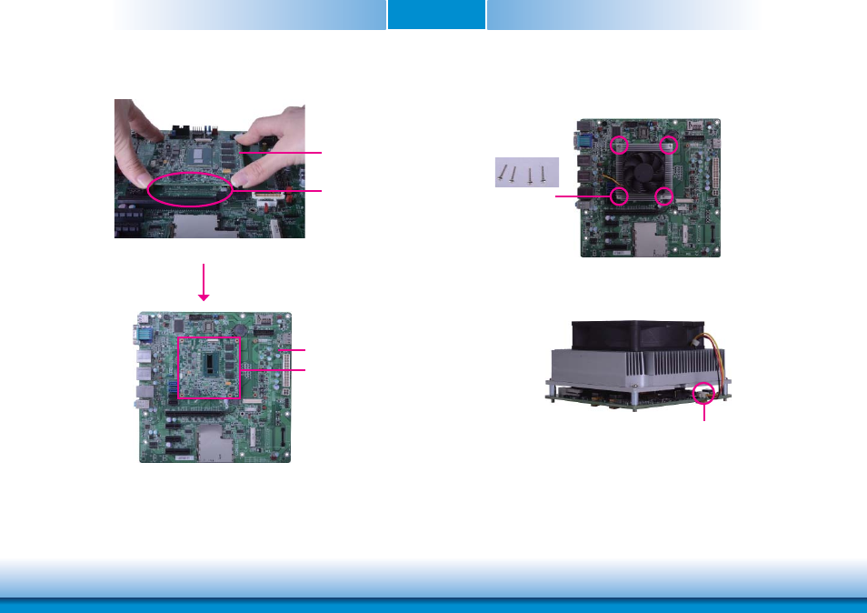
9. Use the provided mounting screws to secure HU968 with heat sink to the carrier board
and then connect the cooling fan’s cable to the fan connector on HU968. The photo below
shows the locations of the long mounting screws.
Long screws
10. And then connect the cooling fan’s cable to the fan connector on HU968.
Fan connector
8. Verify that the module is firmly seated onto the COM Express connectors of the carrier
board.
The module is completely
seated on the carrier board
HU968
Carrier board
HU968
See also other documents in the category DFI Hardware:
- ES300 (2 pages)
- U340 Series (2 pages)
- VS Series (2 pages)
- BT9A3 (57 pages)
- CD9A3 series (60 pages)
- CD905-B series (68 pages)
- BT700 (71 pages)
- BT700 (71 pages)
- CD905-B2600 (63 pages)
- CD905-B2800 (63 pages)
- CP908-B (104 pages)
- CR908-B (68 pages)
- HR908-B (66 pages)
- ML905-B11C/B16C (76 pages)
- KB968 (68 pages)
- LR905-B18S (93 pages)
- OT905-B series (61 pages)
- CM960-B (1 page)
- CM901-B (72 pages)
- CP900-B (130 pages)
- NP905-B16C (125 pages)
- CR900-B (73 pages)
- CR902-BL (75 pages)
- CR901-B (69 pages)
- CR960-QM77 (81 pages)
- HM920-QM87 (98 pages)
- G5C900-B106 (118 pages)
- HM960-QM87 (101 pages)
- HM961-QM87 (95 pages)
- HR900-B (102 pages)
- HR902-BL (75 pages)
- FS700 (17 pages)
- QB702-B (47 pages)
- QB700-B (73 pages)
- COM100-B (32 pages)
- QB701-B (73 pages)
- NP900-B16C (121 pages)
- COM101-BAT (32 pages)
- COM630-B (50 pages)
- COM330-B (57 pages)
- Q7-100 (31 pages)
- Q7-951 (46 pages)
- Q7A-551 (23 pages)
- Q7X-151 (30 pages)