Chapter 3 – DFI HU968 User Manual
Page 18
www.dfi .com
Chapter 3 Hardware Installation
18
Chapter 3
Signal
Pin#
Module Pin Type Pwr Rail /Tolerance
HU968
Carrier Board
Description
0 /S
O
26
C
C C
l
C
0
ȟ
ȟ
ȟ
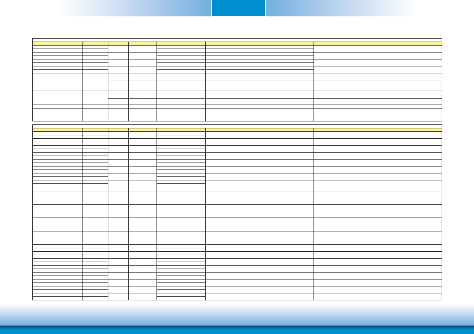
DDI Signals Descriptions
DDI3_PAIR0+
C39
NA
DDI3_PAIR0-
C40
NA
DDI3_PAIR1+
C42
NA
DDI3_PAIR1-
C43
NA
DDI3_PAIR2+
C46
NA
DDI3_PAIR2-
C47
NA
DDI3_PAIR3+
C49
NA
DDI3_PAIR3-
C50
NA
I/O PCIE
AC coupled on Module
NA
DP AUX+ function if DDI3_DDC_AUX_SEL is no connect
I/O OD CMOS
3.3V / 3.3V
NA
HDMI/DVI I2C CTRLCLK if DDI3_DDC_AUX_SEL is pulled high
I/O PCIE
AC coupled on Module
NA
DP AUX- function if DDI3_DDC_AUX_SEL is no connect
I/O OD CMOS
3.3V / 3.3V
NA
HDMI/DVI I2C CTRLDATA if DDI3_DDC_AUX_SEL is pulled high
DDI3_HPD
C44
I CMOS
3.3V / 3.3V
NA
DDI Hot-Plug Detect
DDI3_DDC_AUX_SEL
C38
I CMOS
3.3V / 3.3V
NA
Selects the function of DDI3_CTRLCLK_AUX+ and DDI3_CTRLDATA_AUX-.
DDI[n]_DDC_AUX_SEL shall be pulled to 3.3V on the Carrier with a 100K Ohm
resistor to configure the DDI[n]_AUX pair as the DDC channel.
Carrier DDI[n]_DDC_AUX_SEL should be connected to pin 13 of the DisplayPort
Signal
Pin#
Module Pin Type Pwr Rail /Tolerance
HU968
Carrier Board
Description
USB0+
A46
USB0-
A45
USB1+
B46
USB1-
B45
USB2+
A43
USB2-
A42
USB3+
B43
USB3-
B42
USB4+
A40
USB4-
A39
USB5+
B40
USB5-
B39
USB6+
A37
USB6-
A36
USB7+
B37
USB7-
B36
USB_0_1_OC#
B44
I CMOS
3.3V Suspend/3.3V
PU 10k to 3V3_DU
Connect to Overcurrent of USB Power Switch
USB over-current sense, USB channels 0 and 1. A pull-up for this line
shall be present on the Module. An open drain driver from a USB
current monitor on the Carrier Board may drive this line low. Do not
pull this line high on the Carrier Board.
USB_2_3_OC#
A44
I CMOS
3.3V Suspend/3.3V
PU 10k to 3V3_DU
Connect to Overcurrent of USB Power Switch
USB over-current sense, USB channels 2 and 3. A pull-up for this line
shall be present on the Module. An open drain driver from a USB
current monitor on the Carrier Board may drive this line low. Do not
pull this line high on the Carrier Board.
USB_4_5_OC#
B38
I CMOS
3.3V Suspend/3.3V
PU 10k to 3V3_DU
Connect to Overcurrent of USB Power Switch
USB over-current sense, USB channels 4 and 5. A pull-up for this line
shall be present on the Module. An open drain driver from a USB
current monitor on the Carrier Board may drive this line low. Do not
pull this line high on the Carrier Board.
USB_6_7_OC#
A38
I CMOS
3.3V Suspend/3.3V
PU 10k to 3V3_DU
Connect to Overcurrent of USB Power Switch
USB over-current sense, USB channels 6 and 7. A pull-up for this line
shall be present on the Module. An open drain driver from a USB
current monitor on the Carrier Board may drive this line low. Do not
pull this line high on the Carrier Board.
USB_SSTX0+
D4
AC Coupling capacitor
USB_SSTX0-
D3
AC Coupling capacitor
USB_SSRX0+
C4
USB_SSRX0-
C3
USB_SSTX1+
D7
AC Coupling capacitor
USB_SSTX1-
D6
AC Coupling capacitor
USB_SSRX1+
C7
USB_SSRX1-
C6
USB_SSTX2+
D10
NA
USB_SSTX2-
D9
NA
USB_SSRX2+
C10
NA
USB_SSRX2-
C9
NA
USB_SSTX3+
D13
NA
USB_SSTX3-
D12
NA
USB_SSRX3+
C13
NA
USB_SSRX3-
C12
NA
ȟ
ȟ
ȟ
O PCIE
AC coupled on Module
Connect 90ಳ @100MHz Common Choke in series and ESD suppressors to GND to USB
connector
Additional transmit signal differential pairs for the SuperSpeed USB data path.
I PCIE
AC coupled off Modul
Connect 90ಳ @100MHz Common Choke in series and ESD suppressors to GND to USB
connector
Additional receive signal differential pairs for the SuperSpeed USB data path.
O PCIE
AC coupled on Module
Additional transmit signal differential pairs for the SuperSpeed USB data path.
I PCIE
AC coupled off Modul
DDI 3 Pair 0 differential pairs
DDI 3 Pair 2 differential pairs
O PCIE
DDI 3 Pair 1 differential pairs
DDI3_CTRLCLK_AUX+
C36
DDI3_CTRLCLK_AUX-
C37
O PCIE
AC coupled off Module
O PCIE
AC coupled off Module
DDI 3 Pair 3 differential pairs
AC coupled off Module
O PCIE
AC coupled off Module
I/O USB
3.3V Suspend/3.3V
Connect 90ಳ @100MHz Common Choke in series and ESD suppressors to GND to USB
connector
USB differential pairs 7, USB7 may be configured as a USB client or as a host, or both, at the
Module designer's discretion.(CR901-B default set as a host)
Additional receive signal differential pairs for the SuperSpeed USB data path.
O PCIE
AC coupled on Module
Additional transmit signal differential pairs for the SuperSpeed USB data path.
I PCIE
AC coupled off Modul
Additional receive signal differential pairs for the SuperSpeed USB data path.
I/O USB
I/O USB
3.3V Suspend/3.3V
Connect 90ಳ @100MHz Common Choke in series and ESD suppressors to GND to USB
connector
USB differential pairs 2
I/O USB
3.3V Suspend/3.3V
Connect 90ಳ @100MHz Common Choke in series and ESD suppressors to GND to USB
connector
USB differential pairs 1
I/O USB
3.3V Suspend/3.3V
Connect 90ಳ @100MHz Common Choke in series and ESD suppressors to GND to USB
connector
USB differential pairs 6
3.3V Suspend/3.3V
Connect 90ಳ @100MHz Common Choke in series and ESD suppressors to GND to USB
connector
USB differential pairs 4
I/O USB
3.3V Suspend/3.3V
Connect 90ಳ @100MHz Common Choke in series and ESD suppressors to GND to USB
connector
USB differential pairs 3
I/O USB
3.3V Suspend/3.3V
Connect 90ಳ @100MHz Common Choke in series and ESD suppressors to GND to USB
connector
USB differential pairs 5
USB Signals Descriptions
I/O USB
3.3V Suspend/3.3V
Connect 90ಳ @100MHz Common Choke in series and ESD suppressors to GND to USB
connector
USB differential pairs 0