Hardware installation – Dataprobe iPIO-8 Operation Manual User Manual
Page 2
iPIO-8
Page 2
Hardware Installation
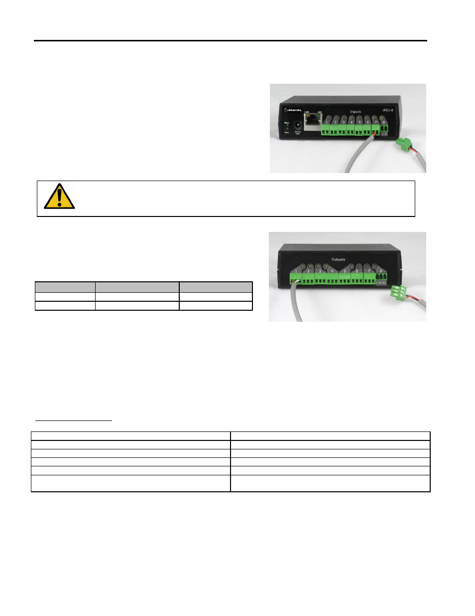
Inputs
Connect the inputs to the iPIO-8 using the screw terminals.
Inputs can be either dry relay or switch contacts, or a +VDC
voltage (3 to 30 V), referenced to a common ground.
Screw terminals are removable for easy installation.
Terminals for each circuit are marked + and G. When
connecting dry relay contacts, the polarity is not significant.
The iPIO-8 is Factory set for Dry Contact Input Only.
Prior to Connecting +VDC, Resistor Pack PU2 must be removed.
Contact Dataprobe Technical Support for Details
When connecting +VDC, connect the positive voltage to the
terminal marked + and the negative or ground to the
terminal marked G.
Status
Dry Relay
DC Voltage
Open
Open
>3VDC
Closed
Closed
<=0VDC
Input Specification
Dry Contact (common ground)
or Wet ±30VDC Max
Relays
Connect to the iPIO-8 relays using the screw terminals, as illustrated. Relays are Form C. Connect to
the Common (C), Normally Closed (NC) and Normally Open (NO) as marked. When the iPIO-8 relay is
in the Open Condition, the Common is connected to the Normally Open. In the Closed state, the
Common and Normally Closed are connected.
Relay Specifications
Rating (resistive)
0.5 A 120 VAC or 1 A 24 VDC
Maximum Carrying Current
2 A
Maximum Switching Power
60 AV, 24 W
Maximum Switching Voltage
120 VAC/60 VDC
Maximum Switching Current
1A
Life Expectancy
5 Million Operations Mechanical.
100K Operations at rated load
Switching Higher Current
The ELK-912-
2 is a two relay board to provide higher current switching for several of Dataprobe’s
remote control products. Each ELK-912-2 is two independent relays, each with screw terminal
connections. The relay boards can be separated in to individual relays as required for mounting.
To use the ELK-912-2 with the iPIO-8, connect the relay board to the Output connections of the iPIO-8
as shown below.