Section 4: electrical installation, 1 power/signal connections, Signal in – Daktronics Sportsound Indoor (SSN-100/150) User Manual
Page 15: Section 4, Electrical installation, Power/signal connections
Electrical Installation
9
Pin 1 = Shield
Pin 2 = + (Red)
Pin 3 = - (Black)
Section 4:
Electrical Installation
CAUTION – RISK OF ELECTRIC SHOCK: Only qualified individuals should perform power routing
and termination to the system. It is the responsibility of the electrical contractors to ensure that all
electrical work meets or exceeds local and national codes. Failure to follow installation guidelines will
result in audible noise on the sound system and possible damage to internal components.
Note: This product is not provided with mains disconnect. Customer shall provide disconnect at
sound system location that meets or exceeds local and national electrical codes.
4.1 Power/Signal Connections
Reference Drawings:
Riser; Standard Indoor Sound System; SSN-150 ................................ Drawing C-1144831
Riser; Standard Indoor Sound System; SSN-100 ................................ Drawing C-1152437
Drawing C-1144831 in Appendix A details power and signal connections between the
control enclosure, sound cabinet, and control rack of the Sportsound indoor sound system.
Signal IN
1. Install an XLR signal input plate (part # EC-1244)
near the announcer’s location. The installation
subcontractor is responsible for providing a 1-gang
receptacle box to mount the signal input plate.
2. Terminate 1 pair, 22 AWG
signal cable (part # W-1615)
to the signal input plate
(Figure 11) as follows:
Note: This is a soldered connection and requires a
qualified technician to terminate.
3. Route signal cable in conduit from the
signal input plate to the control enclosure.
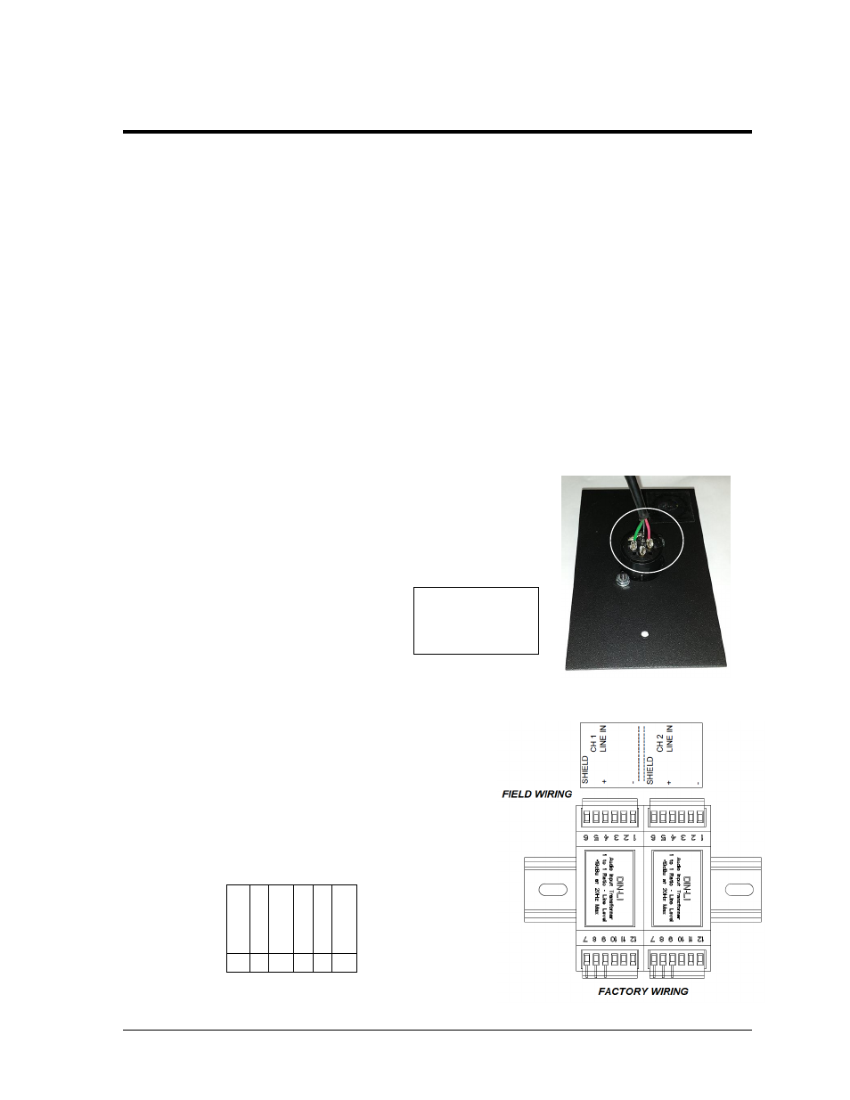
4. Unlock and open the door of the control
enclosure, and terminate the signal cable
to the CH1 transformer per the labels, as
shown in Detail “C” of Drawing C-
1144831, Figure 12, and the table below.
Note: If there is another control location,
signal may also be connected to CH2.
Figure 11: Signal Input Plate
Figure 12: Signal Termination
S
h
ie
ld
+
(R
E
D
)
- (
B
L
K
)
6 5 4 3 2 1