Daktronics AF-3400-64-R,A User Manual
Page 34
2. Disconnect power.
3. Remove all power and signal connections from the board. “Locked”
connectors are released by pushing apart the latches, and then carefully
pulling them from the jack. When replacing the board, it is helpful to have
the cables labeled as to which was removed from which connector.
4. Remove each of the six screws holding the board in place.
5. Follow the previous steps in reverse order to install a new controller board.
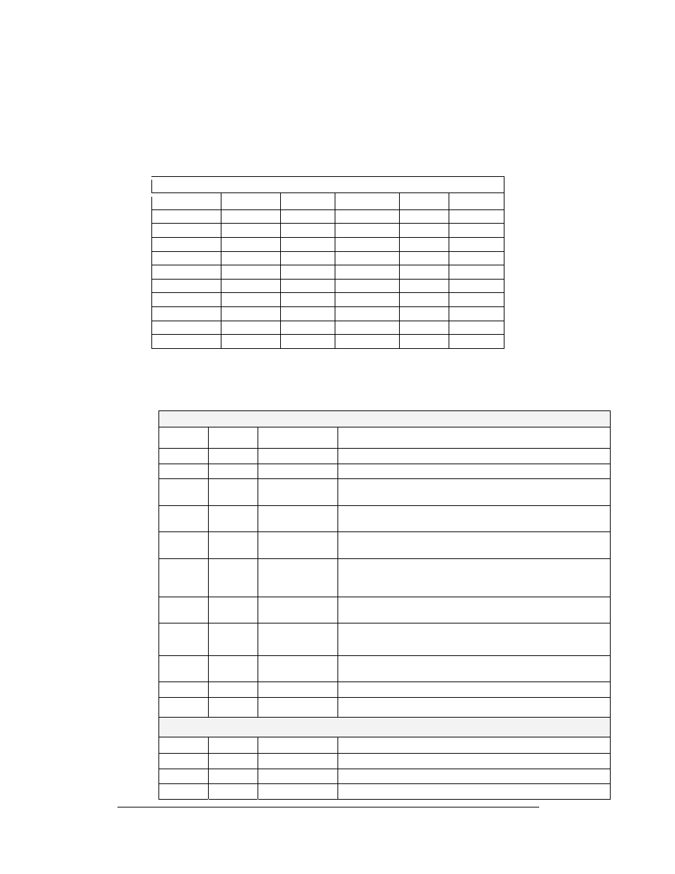
Four diagnostic LEDs are located on the controller; the table below shows what each
LED denotes:
CPU
LED Color
Function Operation
DS1
Red
CAN TxD
Flashes when controller is transmitting CAN information.
DS2
Red
CAN RxD
Flashes when controller is receiving CAN information.
DS3
Red
System Reset
Off when controller is functioning properly. Flashes at 1.5-
second rate if controller is not resetting the watchdog timer.
DS4
Red
Run
A steady flash indicates the controller is running properly.
Normal flash rate is about once per second.
DS5 Red
U15
Programmed
On when U15 contains a valid logic program.
DS7
Red
Link
On when Ethernet interface is in the link-up condition.
Flashes when the Ethernet chip detects transmits or
receives activity.
DS8
Red
Speed
On when the Ethernet interface is at 100Mbps. Off when
the Ethernet interface is at 10Mbps.
DS9
Red
Duplex
On when the Ethernet interface is at full duplex. Off when
the Ethernet interface is at half-duplex.
DS10
Red
Collision
Flashes when the Ethernet interface detects a collision in
half-duplex.
DS12
Red
+2.5V
On when +2.5V power supply is functioning.
DS13
Red
+3.3V
On when +3.3V power supply is functioning.
Product Board
LED Color
Function Operation
DS1
Green
+5V
On when +5V power supply is functioning.
DS2
Green
+3.3V
On when +3.3V power supply is functioning.
DS3
Yellow
COM1 TxD
Flashes when transmitting serial information.
Controller Address Settings
Address
Upper
Lower
Address
Upper
Lower
Test Mode
0 0 10
0 A
1
0 1 11
0 B
2
0 2 12
0 C
3
0 3 13
0 D
4
0 4 14
0 E
5
0 5 15
0 F
6
0 6 16
1 0
7
0 7 17
1 1
8
0 8 …
… …
9
0 9 240
F 0
Maintenance and Troubleshooting
4-6