3 testing and replacing a prolink router, 4 replacing plr power supplies – Daktronics 4200 Series Digital Billboard User Manual
Page 22
18
6.3 Testing and Replacing a ProLink Router
A ProLink Router (PLR) sends the signal from the DMP-8065 to the modules via SATA cables.
For the 4200 series, the PLRs have redundant power.
Testing a PLR
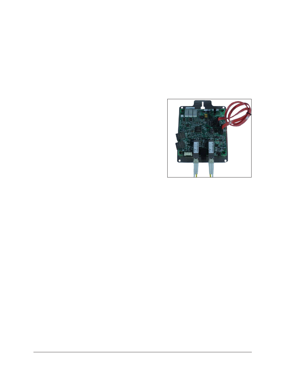
Before replacing a PLR, it may be beneficial to perform a self-test. To perform this test:
1. Connect a duplex fiber cable from Fiber Port A to Fiber Port B. Refer to Figure 14.
2. Connect a working SATA cable from SATA Port A to SATA Port B.
3. Connect the power cable to the PLR. This will start the PLR self-test.
4. Wait for the test to complete. This may take up
to 90 seconds. If the PLR has successfully sends
and receives data through each of the ports, the
letters P.A.S will appear on the Seven Segment
Display. If the letters E.r.r appear, the Seven
Segment Display will show the port numbers
with issues. Refer to the ProLink Router 6050
Manual in Appendix A for a full list of error
codes.
5. Replace the PLR if the error persists after
troubleshooting.
Replacing a ProLink Router
Required Tools: Phillips screwdriver
1. Access the interior of the display by using the
steps provided in Section 4.
2. Disconnect the PLR SATA and power cables.
3. Using a Phillips screwdriver, loosen the PLR assembly set screw.
4. Lift the PLR assembly to disengage it from the display.
5. Reverse Steps 2 - 4 to install the new PLR.
6. Verify the cables are properly seated.
6.4 Replacing PLR Power Supplies
Each PLR has a power supply and a redundant power supply. If one power supply fails, the PLR
will still function on the redundant power supply. To replace a failed PLR power supply:
1. Disconnect any power cables to the power supply and from that power supply to the
PLR.
2. Pull the power supply tab. Refer to Figure 13.
3. Rotate the power supply forward and lift it off of the pegs.
4. Reverse Steps 1 - 3 to install a replacement power supply.
Figure 14: ProLink Router Connected for
Self-Test
Testing and Replacing Display Components