7 reinstalling a module (rear access) – Daktronics 4200 Series Digital Billboard User Manual
Page 19
15
8. Remove the module by pushing it away from the display face, pivoting and rotating it 90
degrees and pulling it through the face sheet.
Note: Ensure the louver blades run lengthwise when pulling the module through the
display face so they do not get damaged by the face sheet.
9. Repair or replace the module as needed.
10. Reverse Steps 1 - 8 to reinstall the module.
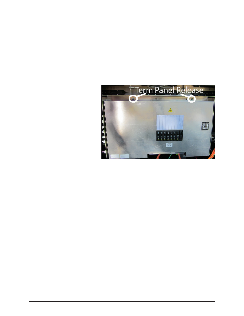
5.6 Removing a Module from Behind a Term Panel (Rear Access)
Required Tools: Phillips head screwdriver,
1
/
8
" Allen wrench, module lanyard
1. Locate the two release screws along the top of the term panel. Refer to Figure 11.
2. Use the Phillips head
screwdriver to turn
each screw counter-
clock wise until the
term panel disengages
from the display.
3. While holding the
term panel, allow it to
slowly hinge forward.
4. Follow the steps in
Section 5.4 to remove
and reinstall a module.
5. Reverse Steps 1 - 3 to
replace the term panel.
5.7 Reinstalling a
Module (Rear Access)
1. Rotate and carefully guide the module through the module opening.
Note: To ensure proper alignment, verify the word TOP printed on the back of the module is
to the top left of the module.
2. Once the module is through the display face, align the module with the face sheet so the
gravity load pegs fit in the gravity load peg holes. Ensure the lanyard or cables do not pinch
between the module and the display.
3. After the module is in place, use the bottom module lanyard rings or the lanyard to pull the
module firmly against the face sheet.
4. With a
1
/
8
" hex wrench, turn the bottom latch gear approximately a quarter-turn counter-
clock wise to engage the latch.
5. Use the top module lanyard rings or the lanyard to pull the module firmly against the face
sheet.
6. With a
1
/
8
" hex wrench, turn the bottom latch gear approximately a quarter-turn
counterclockwise to engage the latch.
7. Use the top module lanyard rings or the lanyard to pull the module firmly against the face
sheet.
8. With a
1
/
8
" hex wrench, turn the top latch gear approximately a quarter-turn
counterclockwise to engage the latch.
9. Connect the SATA and power cables to the back of the module.
Figure 11: Term Panel With Turnkeys Labeled
Module Testing and Removal