Section 3: maintenance, 1 led diagnostics, Section 3 – Daktronics Ethernet Bridge Radio (EBR) 900 MHz (0A-1327-1111) and 2.4GHz (A-3446) User Manual
Page 9: Maintenance, Led diagnostics
Maintenance 5
Section 3: Maintenance
3.1 LED Diagnostics
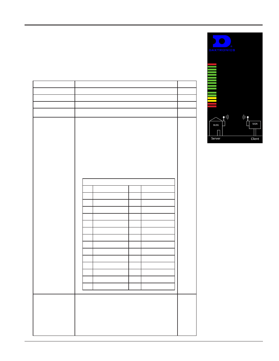
Use the label affixed to the radio, shown in
Figure 11 and Figure 19, and the
16 diagnostic LEDs on boards inside the housing of both the server and client
radios to determine whether the radio is linking properly and which channel is
currently being used.
The following chart also describes the diagnostic LEDs’ functions:
Power
RF Receive
RF Transmit
Ethernet Link
Channel
Sum values to
determine channel
32
1
6
8
4
2
1
BEST
FAIR
Link Quality
POOR
Minimum Distance - 20 ft
Maximum Distance - 1500 ft
Minimum Height - 20 ft
Mount in Direct Line of Sight
Mount Both Radios Outdoors
Mount radios with antennas vertical and
provide free and clear radiation pattern
Figure 11: Radio Label
Name
Function
Color
Power
Unit has power and has successfully booted.
Red
RF TX
Radio transmission is occurring.
Green
RF RX
Radio reception is occurring.
Green
Ethernet Link
The Ethernet Port has a valid Ethernet connection.
Green
CH 1
CH 2
CH 4
CH 8
CH 16 (not used with
900 MHz radios)
CH 32 (not used)
By adding the numbers that are lit, the user can
determine the current radio channel.
2.4 GHz Radios
0
Auto Mode
15
2.445833 GHz
1
2.416667 GHz
16
2.447917 GHz
2
2.418750 GHz
17
2.450000 GHz
3
2.420833 GHz
18
2.452083 GHz
4
2.422917 GHz
19
2.454167 GHz
5
2.425000 GHz
20
2.456250 GHz
6
2.427083 GHz
21
2.458333 GHz
7
2.429167 GHz
22
2.460417 GHz
8
2.431250 GHz
23
2.462500 GHz
9
2.433333 GHz
24
2.464583 GHz
10
2.435417 GHz
25
2.466667 GHz
11
2.437500 GHz
26
2.468750 GHz
12
2.439583 GHz
27
2.470833 GHz
13
2.441667 GHz
28
2.472917 GHz
14
2.443750 GHz
29
2.475000 GHz
900MHz Radios
1
903.12500 MHz
7
915.62500 MHz
2
905.20833 MHz
8
917.70833 MHz
3
907.29167 MHz
9
919.79167 MHz
4
909.37500 MHz
10
921.87500 MHz
5
911.45833 MHz
11
923.95833 MHz
6
913.54167 MHz
12
926.04167 MHz
Green
Link Quality Meter:
The more LEDs that
are lit, the higher the
link quality
Excellent link quality
No retransmissions
Green
Very good link quality Few retransmissions
Green
Good link quality
Occasional retransmissions
Amber
Fair link quality
Some retransmissions
Amber
Poor link quality
Many retransmissions
Red
No link quality
No link available
Red