Section 2: installation, 1 system/cable requirements, Section 2 – Daktronics Ethernet Bridge Radio (EBR) 900 MHz (0A-1327-1111) and 2.4GHz (A-3446) User Manual
Page 7: Installation, System/cable requirements, Installation 3, Displays or a dhcp address for galaxypro, Figure 3: wireless ethernet display layout
Installation 3
Section 2: Installation
The controller has either a default IP address (172.16.192.25) for Galaxy
®
displays or a DHCP address for GalaxyPro
®
Series displays. Once the default IP address is used to connect to the display, it can be changed to a personalized
address. Refer to the display manual for further information on setting an IP address. Various LAN and Internet
service providers (ISP) have differing IP requirements. Consult the network administrator or ISP for more
information. The DHCP address automatically adjusts to suit the local network.
2.1 System/Cable Requirements
In an Ethernet radio system, two radios are required. A server radio transmits/receives signal to/from a
client radio, shown in
Figure 1 and Figure 2, at the display. The server radio connects to the Ethernet LAN
through a DC injector.
Daktronics provides a yellow 20-foot CAT 5e Ethernet cable, which is required to connect the DC injector to
the LAN. The customer must supply a longer cable if it is needed.
Ethernet and power cables are provided to connect the client radio to the display and the server radio to the
DC injector.
A Windows
®
-based computer is required (but not provided) to run Venus
®
1500 control software.
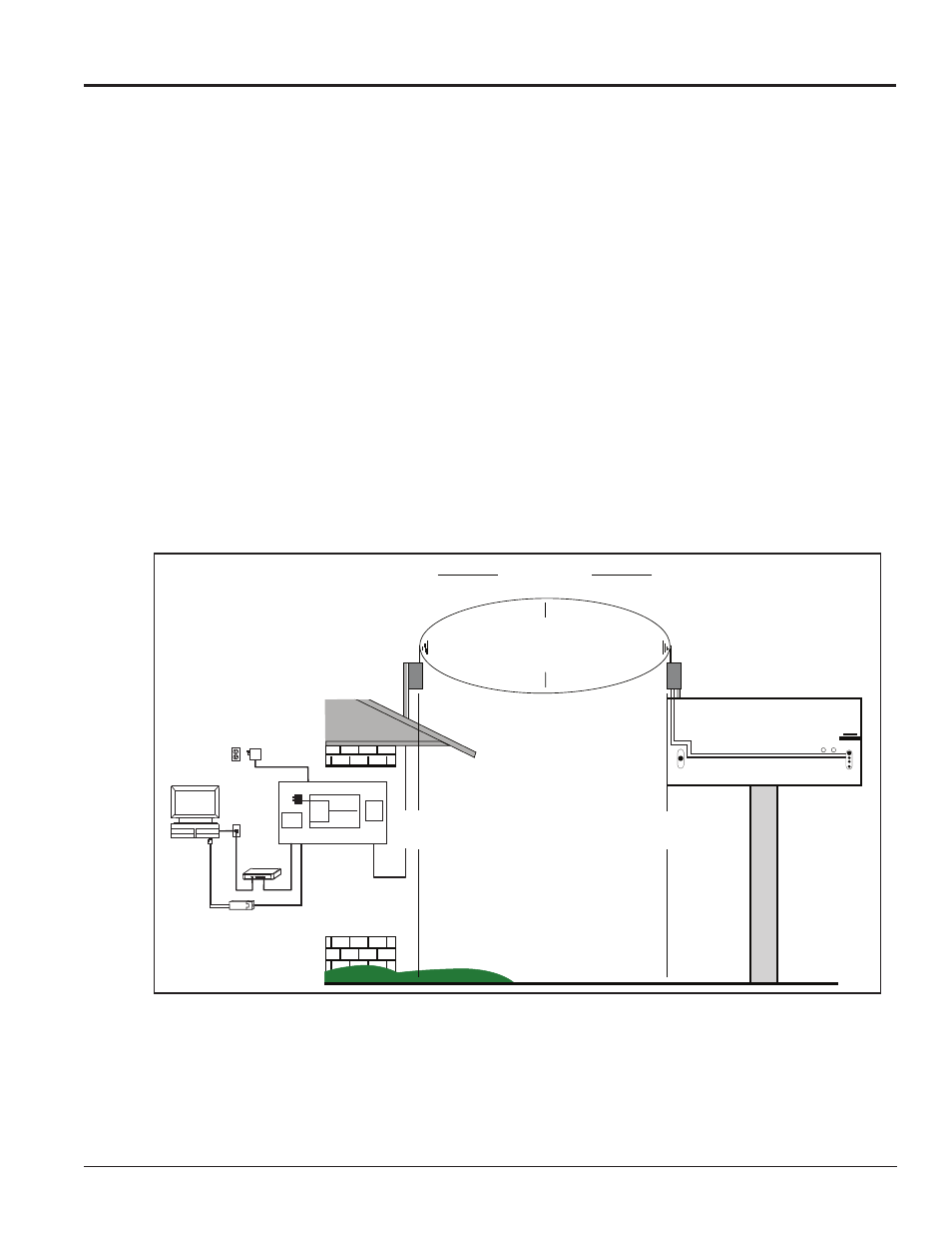
An Ethernet radio-controlled display requires the following connections, refer to
Figure 3 for a system layout:
Server
Radio
Network Connections
Inside Building
Cat-5E 300 ft. max from network switch to radio
Injector of Power over Ethernet
Switch
Hub
RJ45
Computer
Running
Venus 1500
Network Switch
120V AC
AC
Input
Data
Input
Data+VDC
output
▪▪▪▪▪
▪▪▪▪▪
Power
Injector
Splitter
Optional USB to Ethernet Adapter
▲
▲
▲
▲
Recommend
20 Feet
Minimum
- 4- to 26-Foot Radio Transmission Zone Depending on
Distance (900 MHz Radios)
- 1.5- to 13-Foot Radio Transmission Zone
(2.4 GHz Radios)
- Avoid Obstructions Within This Zone
▲
▲
1,500 Feet Maximum
20 Feet Minimum
▲
▲
Recommend
20 Feet
Minimum
PRIMARY DISPLAY - REAR
Client
Radio
PRIMARY
Figure 3: Wireless Ethernet Display Layout