Section 1: introduction, 1 component identification, Section 1 – Daktronics Ethernet Bridge Radio (EBR) 900 MHz (0A-1327-1111) and 2.4GHz (A-3446) User Manual
Page 5: Introduction, Component identification
Introduction 1
Section 1: Introduction
1.1 Component Identification
Ethernet: A technology for high-speed bandwidth connectivity over local area networks (LAN).
Client Radio: This radio receives
signal from the server radio. The
client radio is connected to and
receives power from the display.
Signal between the client and the
display is both transmitted and
received.
Server Radio: This radio is connected
to the local Ethernet network through
a DC injector which provides power
to the radio. It transmits and receives
information to and from the client
radio at the display.
DC Injector: This unit, shown in
Figure 5, receives signal in from the
customer’s network and relays signal
out to the radio. It contains a power
input to power the server radio.
Note: The DC Injector is for indoor
use only.
Optional USB to Ethernet Adapter:
This bypasses complex network
configuration in situations where
simple point-to-point communication
is required. The adapter creates
a secondary network, which is
dedicated for communication with a
Daktronics Galaxy
®
display. Normal network operation is still enabled through the primary network.
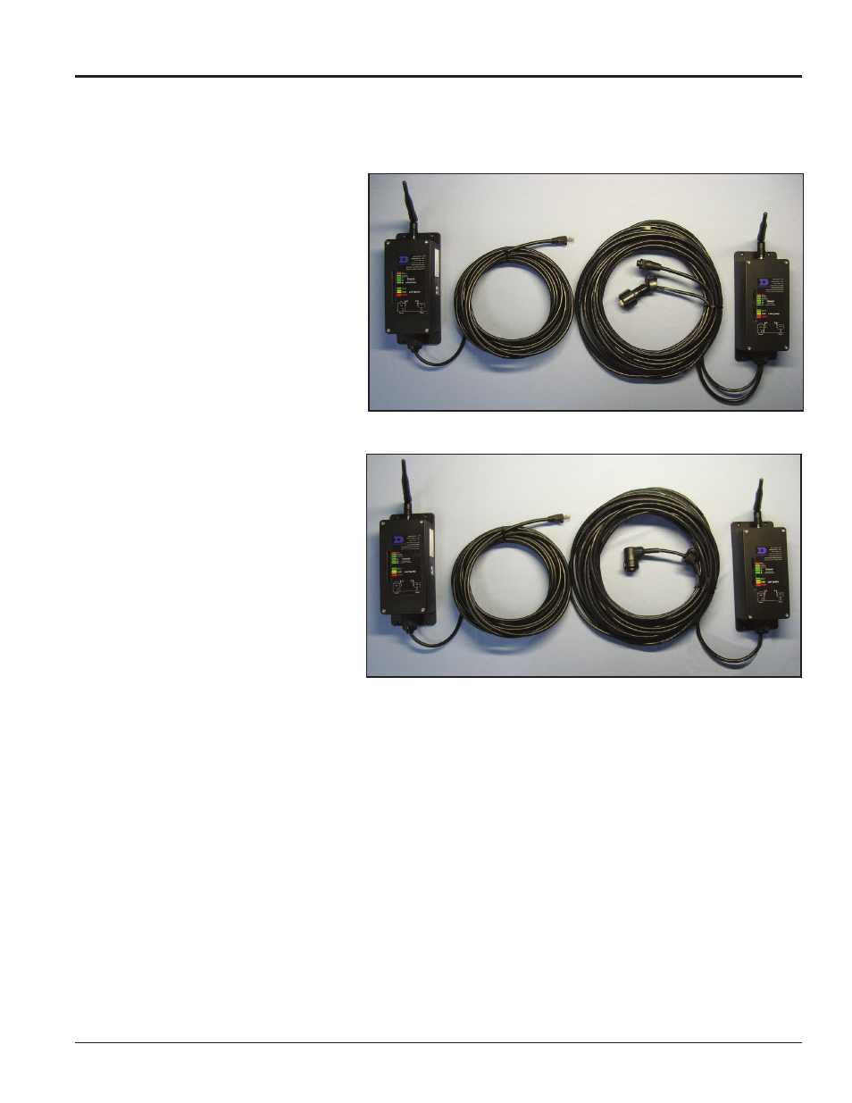
Figure 1: Ethernet Bridge Radios – Two-Wire Client Radio
Figure 2: Ethernet Bridge Radios – Single-Wire (10-pin Quick Connect) Client
Radio