Daktronics Ethernet Bridge Radio (EBR) 900 MHz (0A-1327-1111) and 2.4GHz (A-3446) User Manual
Page 8
4 Installation
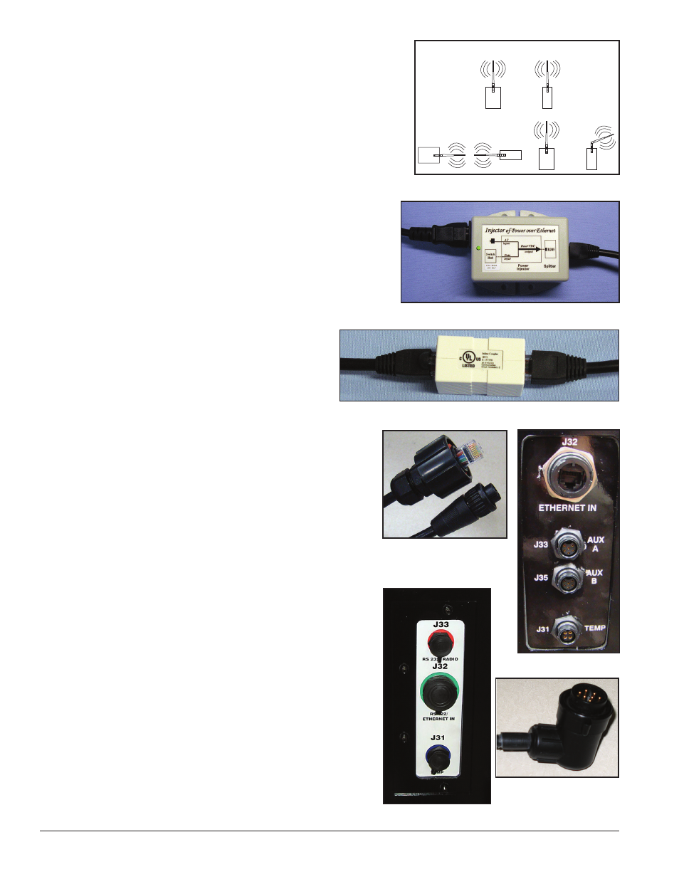
Daktronics recommends radios be mounted with antennas
pointing upward.
Figure 4 illustrates correct and incorrect
antenna placement.
Do not mount the radios with the wire grommet pointing
upward.
There are two types of client radio connectors for Galaxy products
– two wire –
Figure 1 and single wire – Figure 2.
1. A CAT 5e Ethernet cable is routed from the LAN switch/
router to the DC injector.
Note: The DC Injector is for indoor use only.
2. The Ethernet cable connects to the Switch Hub jack on
3. The DC injector is provided with an AC power adapter.
The AC power adapter is connected to the
AC input
jack on the DC Injector and inserted into a 120 VAC
wall outlet.
4. The server radio is provided with a 25 ft.
(7.6 m) attached Ethernet cable. This
Ethernet cable is connected to the
RJ45 jack
on the DC injector.
The maximum distance between the
network switch and server radio is 300 ft.
(91.44 m).
Note: Install a Cat 5e inline coupler, example shown
in
Figure 6, to the end of the server radio cable and
connect it to a high-quality Cat 5e cable.
5. Mount the server radio outdoors for best signal
quality. Indoor mounting significantly reduces
signal quality and can cause communication issues
to the display.
6. Mount the client radio within 25 ft. (7.6 m) of the
input jacks.
7. Route the signal quick-connect cables from the
enclosure to the rear of the display.
The cable from the enclosure to the display can be
routed through conduit or through the display pole,
and should be secured to protect it from weather or
vandalism. Provide drip loops to prevent water
migration to display quick-connect interface board.
8. Connect the quick-connect cables to the top two (J32
examples. Or connect the quick-connect cable to the
middle jack if the display is a single-cable design, as
shown in
Antenna Alignment Guidelines
Right
Wrong
Wrong
Figure 4: Antenna Alignment Examples
Figure 5: DC Injector
Figure 6: Extend Cat 5e Cable Using a Cat 5e Inline Coupler
Figure 7: Quick-Connect
Cables - Two-Wire Design
Figure 8: Input Jacks
Figure 9: Input Jacks
Figure 10: 10-Pin Quick-
Connect Cable - Single-
Wire Design