Daktronics Ethernet Bridge Radio (EBR) 900 MHz (0A-1327-1111) and 2.4GHz (A-3446) User Manual
Page 12
8
Troubleshooting and Radio Diagnostics
If a disconnect state is noted on the Network Map, check how the radios are installed. Are they installed
correctly with both antennas pointing upward and are the radios mounted high
enough to eliminate obstructions like semi-trailer traffic? Or are there
obstructions like trees between radio installations? Are the radios installed at an
appropriate distance to one another?
All of these can disrupt signal strength. If the radios are installed correctly, but
transmission problems still exist, call the Daktronics Help Desk at 866-343-3122
for further instruction.
Observe the diagrams that represent the Server and Client radios.
The bars reflect Signal Strength and are directly affected by the Block Error Rate
in Advanced Diagnostics. Signal Strength is
strongest when all five bars are green, as
shown in
When signal strength is weak, as shown in
Figure 17, bar 1 is red, and bars 2 and 3 are
amber.
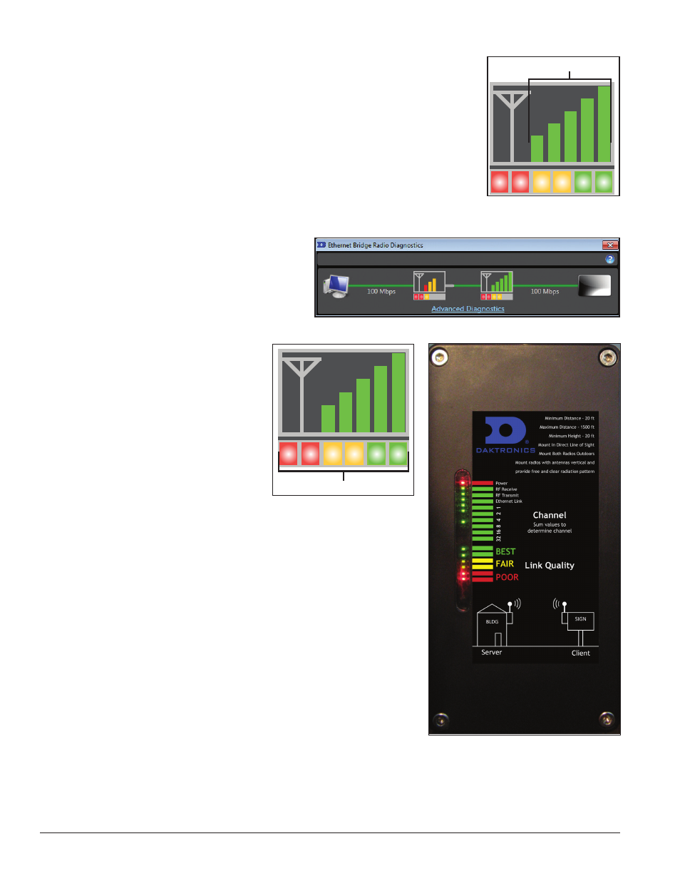
The colored boxes below each Signal
Strength diagram, shown
in
Figure 18, correspond to the Link
Quality LEDs, shown in
Figure 19,
found on the board in each radio.
When both green boxes at the right
side of each diagram are lit, you
know that communication between
radios is good.
If neither green box is lit, check
how the radios are installed. Are
they installed correctly with both
antennas pointing upward and
are the radios mounted high enough to eliminate obstructions like
semi-trailer traffic? Or are there obstructions like trees between radio
installations? Are the radios installed at an appropriate distance to
one another?
All of these can disrupt signal strength. If the radios are installed
correctly, but transmission problems still exist, call the Daktronics
Help Desk at 866-343-3122 for further instruction.
Signal Strength Bars
Figure 16: Server and Client
Radio Signal Strength Bars
Figure 17: Weak Signal Strength
Status LEDs
Figure 18: Server and Client
Radio Status LEDs
Figure 19: Link Quality LEDs and Label
Found on Server and Client Radios