Base station (rc-100), 6 segmentation & digit designation, 7 schematics – Daktronics Tuff Sport Indoor LED Scoreboards User Manual
Page 20: Segmentation & digit designation, Schematics
14
Scoreboard Troubleshooting
Base Station (RC-100)
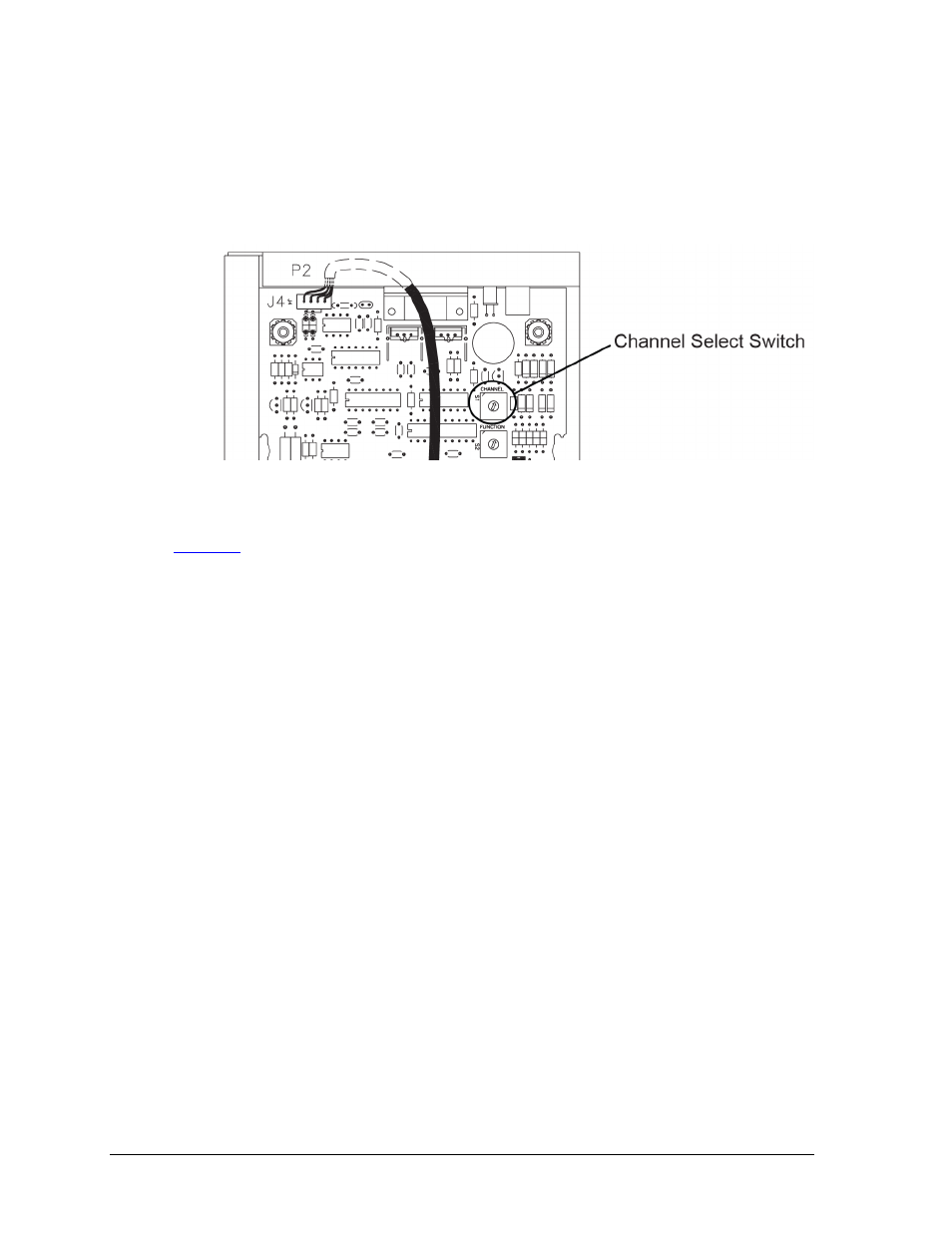
1. Use a small flathead screwdriver to set the S1 switch (Figure 15) to the desired
channel (1-15).
2. Securely close the scoreboard access panel.
3. Enter the correct channel setting and sport code into the RC-100 handheld controller
to test the radio connection.
For more information, refer to the Remote Control System RC-100 All Sport Operation Manual
.
2.6 Segmentation & Digit Designation
In each digit, certain LEDs always go on and off together. These groupings of LEDs are called
segments. Drawing A-38532 in Appendix C details which connector pin is wired to each digit
segment and the wiring color code used throughout the scoreboard.
The Electrical and Signal drawings and Component Location drawings also specify the driver
connectors controlling the digits. Numbers shown in hexagons in the upper half of each digit
indicate which connector is wired to that digit.
2.7 Schematics
For advanced scoreboard troubleshooting and repair, it may be necessary to consult the
schematic drawings. Listed in Appendix B, schematic drawings show detailed power and
signal wiring diagrams of internal display components such as drivers, horn interface cards,
and transformers as well as optional components like TNMCs, radio receivers, and end of
period (EOP) lighting.
Figure 15:
Channel Select Switch (Internal Receiver)