Replacing a driver, Setting the driver address – Daktronics Tuff Sport Indoor LED Scoreboards User Manual
Page 16
10
Scoreboard Troubleshooting
Replacing a Driver
If the driver status indicators do not appear to be working correctly, it may be necessary to
replace the driver.
1. Open the digit panel or scoreboard face panel as described in Section 2.2.
2. Disconnect all connectors from the driver by squeezing together the locking tabs and
pulling the connectors free. It may be helpful to label the cables to know which cable
goes to which connector when reattaching the driver.
3. Remove the wing nuts securing the driver to the driver tray.
4. Carefully lift the driver from the display and place it on a clean, flat surface.
5. Position a new driver over the screws and tighten the nuts.
6. Reconnect all power/signal connectors.
Note: The connectors are keyed and will attach in one way only. Do not attempt to
force the connections.
7. Ensure the driver is set to the correct address (refer to Setting the Driver Address).
8. Close and secure the access panel, then power up and test the scoreboard to see if
changing the driver has resolved the problem.
Setting the Driver Address
Since the same LED drivers can be used for many scoreboard models, each driver must be set
to receive the correct signal input, or address, for the model being used. The way the address
is set depends on the driver type:
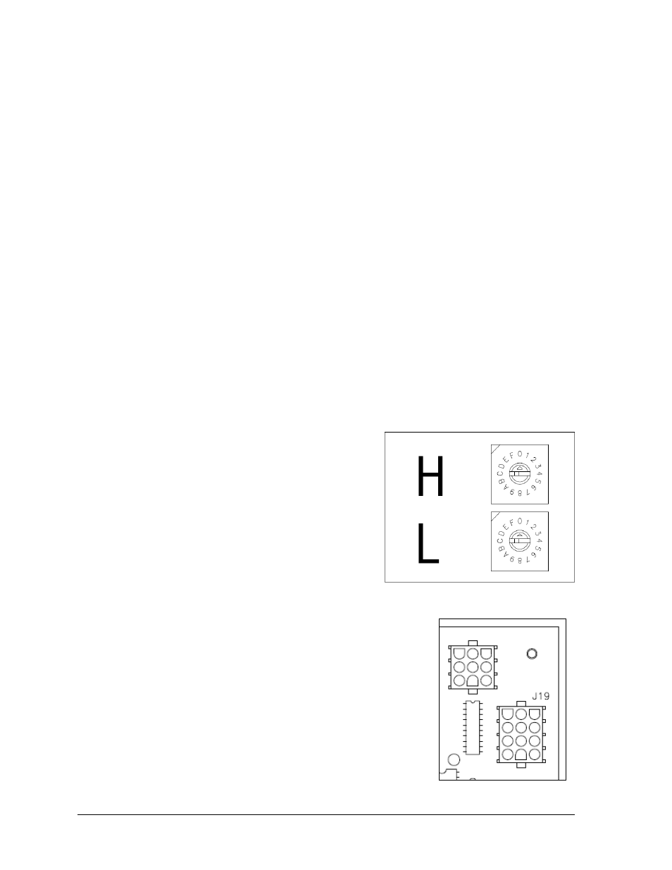
For 16-column “Gyrus” drivers, addresses
are set through the S2 (L) and S3 (H) rotary
switches on the driver (Figure 9) using a
small flathead screwdriver.
Refer to the tables on the following pages to
determine the correct address setting of the
driver(s) in a particular scoreboard model
and see Drawing B-1198765 in Appendix C
for addressing information of driver
addresses 1 – 255.
For older 16-column and 4-column drivers, addresses
are set with jumper wires in a 12-pin plug which mates
with jack J19 on the driver (Figure 10).
It may be possible to reuse the same address plug from
the driver that was replaced. If not, first refer to the
table on the following page to determine the correct
address setting of the driver(s) in a particular
scoreboard model. Then see Drawing A-115078 in
Appendix C for a listing of the wire/pin connections
for driver addresses 1 – 128.
Figure 9: Driver Address Dials
Figure 10: Address Jack J19,
16-Column Driver