2 component location & access, Component location & access – Daktronics BB-2102 Tuff Sport Four-Sided Basketball LED Scoreboard User Manual
Page 29
Maintenance & Troubleshooting
23
Problem
Possible Cause
Solution/Items to Check
Scoreboard works, but some
digits do not light
Bad digit or driver
(see solution on previous page)
Incorrect sport code
(see solution on previous page)
Incorrect driver address
(see solution on previous page)
Wrong console controlling
scoreboard
Another console’s radio signal could
be transmitting to the scoreboard.
Radio interference
There may be other radio
transmissions in the area that
overpower the console. If it is not
possible to disable the interfering
device, It may be necessary to run a
wired signal connection instead.
Note: For message center maintenance and troubleshooting for BB-2146 and BB-2147 models,
refer to the SS Series 20mm Indoor Scoreboard Message Centers Installation & Operation
Manual (DD1564453).
5.2 Component Location & Access
All Tuff Sport indoor basketball displays are front-access scoreboards, meaning that internal
electronic components and digits are reached by opening a face panel, an access door, or a
digit panel on the front of the display.
Digit panels are typically held in place on the scoreboard face by two screws. To remove a
digit, simply unfasten the screws and carefully lift it from the cabinet. The power/signal plug
can then be removed from the connector on the back of the digit to completely free the digit
and access internal components.
Remove non-digit access panels by unfastening the top, side or bottom screws holding it in
place. Some panels are hinged and swing open when the screws are removed or loosened.
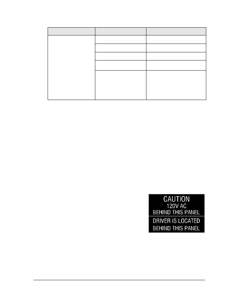
Component location varies with each scoreboard model,
but drivers and power and signal components are
typically mounted inside the scoreboard behind a digit
panel. To locate the driver(s), look for a warning label
similar to that shown in Figure 9.
Refer to the electrical and signal specification drawings in
Appendix B for model-specific component layouts and
access locations.
Figure 9: Power Warning Label
- BB-2104 Tuff Sport Four-Sided Basketball LED Scoreboard BB-2106 Tuff Sport Four-Sided Basketball LED Scoreboard BB-2108 Tuff Sport Four-Sided Basketball LED Scoreboard BB-2124 Tuff Sport Four-Sided Basketball LED Scoreboard BB-2156 Tuff Sport Four-Sided Basketball LED Scoreboard BB-2154 Tuff Sport Four-Sided Basketball LED Scoreboard BB-2147 Tuff Sport Four-Sided Basketball LED Scoreboard BB-2146 Tuff Sport Four-Sided Basketball LED Scoreboard BB-2126 Tuff Sport Four-Sided Basketball LED Scoreboard BB-3102 ColorSmart Four-Sided Basketball LED Scoreboard BB-3104 ColorSmart Four-Sided Basketball LED Scoreboard BB-3106 ColorSmart Four-Sided Basketball LED Scoreboard BB-3108 ColorSmart Four-Sided Basketball LED Scoreboard BB-3147 ColorSmart Four-Sided Basketball LED Scoreboard BB-3146 ColorSmart Four-Sided Basketball LED Scoreboard BB-3124 ColorSmart Four-Sided Basketball LED Scoreboard BB-3126 ColorSmart Four-Sided Basketball LED Scoreboard TN-2501 Tuff Sport Indoor Tennis LED Scoreboard TN-2503 Tuff Sport Indoor Tennis LED Scoreboard TN-2504 Tuff Sport Indoor Tennis LED Scoreboard TN-2505 Tuff Sport Indoor Tennis LED Scoreboard TN-2550 Tuff Sport Indoor Tennis LED Scoreboard TN-2551 Tuff Sport Indoor Tennis LED Scoreboard TN-2552 Tuff Sport Indoor Tennis LED Scoreboard TN-2553 Tuff Sport Indoor Tennis LED Scoreboard TN-2560 Tuff Sport Indoor Multi-Court Tennis LED Scoreboard TN-2561 Tuff Sport Indoor Multi-Court Tennis LED Scoreboard TN-2562 Tuff Sport Indoor Multi-Court Tennis LED Scoreboard TN-2563 Tuff Sport Indoor Multi-Court Tennis LED Scoreboard H-2101 Tuff Sport Hockey LED Scoreboard H-2102 Tuff Sport Hockey LED Scoreboard H-2103 Tuff Sport Hockey LED Scoreboard H-2104 Tuff Sport Hockey LED Scoreboard H-2106 Tuff Sport Hockey LED Scoreboard H-2115 Tuff Sport Hockey LED Scoreboard H-2114 Tuff Sport Hockey LED Scoreboard H-2111 Tuff Sport Hockey LED Scoreboard H-2108 Tuff Sport Hockey LED Scoreboard H-2105 Tuff Sport Four-Sided Hockey LED Scoreboard H-2107 Tuff Sport Four-Sided Hockey LED Scoreboard H-2109 Tuff Sport Four-Sided Hockey LED Scoreboard H-2112 Tuff Sport Four-Sided Hockey LED Scoreboard VB-2101 Tuff Sport Volleyball LED Scoreboard