Daktronics BB-2102 Tuff Sport Four-Sided Basketball LED Scoreboard User Manual
Page 23
Electrical Installation
17
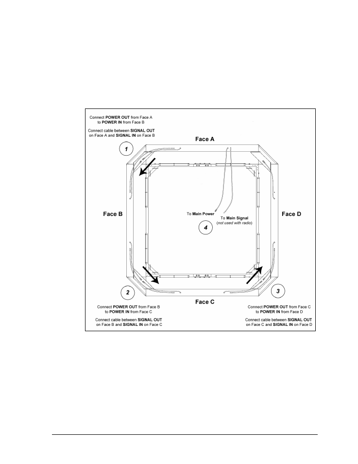
Scoreboard power and signal connectors are located on top of the scoreboard cabinet.
Input cables should be routed to the left, and output cables should be routed to the
right (as viewed from the front). The scoreboard section that will receive main
power/signal is designated “Face A”; all other sections are named in relation to it.
Power and signal flows to the right around the display from face output to face input.
Figure 7 shows the power and signal flow between sections. Main power and signal are
terminated last (refer to Sections 4.3 and 4.5, respectively).
Backlit ad panel and message center connectors are located on the sides of the
cabinets. Inputs are on the left, and outputs are on the right (as viewed from the front).
Each message center requires its own power input, while backlit ad panels may be
daisy-chained together for power, like scoreboards. Message center signal connections
use 6-pin RJ45 quick connect cables; main signal may be wired or wireless.
Refer to Drawing A-154599 in Appendix E for connection details of power and signal
from one backlit ad panel or message display section to the next. Refer to Drawing
A-822860 for additional message center connection details.
Figure 6: Scoreboard Power & Signal Connection, Top View
- BB-2104 Tuff Sport Four-Sided Basketball LED Scoreboard BB-2106 Tuff Sport Four-Sided Basketball LED Scoreboard BB-2108 Tuff Sport Four-Sided Basketball LED Scoreboard BB-2124 Tuff Sport Four-Sided Basketball LED Scoreboard BB-2156 Tuff Sport Four-Sided Basketball LED Scoreboard BB-2154 Tuff Sport Four-Sided Basketball LED Scoreboard BB-2147 Tuff Sport Four-Sided Basketball LED Scoreboard BB-2146 Tuff Sport Four-Sided Basketball LED Scoreboard BB-2126 Tuff Sport Four-Sided Basketball LED Scoreboard BB-3102 ColorSmart Four-Sided Basketball LED Scoreboard BB-3104 ColorSmart Four-Sided Basketball LED Scoreboard BB-3106 ColorSmart Four-Sided Basketball LED Scoreboard BB-3108 ColorSmart Four-Sided Basketball LED Scoreboard BB-3147 ColorSmart Four-Sided Basketball LED Scoreboard BB-3146 ColorSmart Four-Sided Basketball LED Scoreboard BB-3124 ColorSmart Four-Sided Basketball LED Scoreboard BB-3126 ColorSmart Four-Sided Basketball LED Scoreboard TN-2501 Tuff Sport Indoor Tennis LED Scoreboard TN-2503 Tuff Sport Indoor Tennis LED Scoreboard TN-2504 Tuff Sport Indoor Tennis LED Scoreboard TN-2505 Tuff Sport Indoor Tennis LED Scoreboard TN-2550 Tuff Sport Indoor Tennis LED Scoreboard TN-2551 Tuff Sport Indoor Tennis LED Scoreboard TN-2552 Tuff Sport Indoor Tennis LED Scoreboard TN-2553 Tuff Sport Indoor Tennis LED Scoreboard TN-2560 Tuff Sport Indoor Multi-Court Tennis LED Scoreboard TN-2561 Tuff Sport Indoor Multi-Court Tennis LED Scoreboard TN-2562 Tuff Sport Indoor Multi-Court Tennis LED Scoreboard TN-2563 Tuff Sport Indoor Multi-Court Tennis LED Scoreboard H-2101 Tuff Sport Hockey LED Scoreboard H-2102 Tuff Sport Hockey LED Scoreboard H-2103 Tuff Sport Hockey LED Scoreboard H-2104 Tuff Sport Hockey LED Scoreboard H-2106 Tuff Sport Hockey LED Scoreboard H-2115 Tuff Sport Hockey LED Scoreboard H-2114 Tuff Sport Hockey LED Scoreboard H-2111 Tuff Sport Hockey LED Scoreboard H-2108 Tuff Sport Hockey LED Scoreboard H-2105 Tuff Sport Four-Sided Hockey LED Scoreboard H-2107 Tuff Sport Four-Sided Hockey LED Scoreboard H-2109 Tuff Sport Four-Sided Hockey LED Scoreboard H-2112 Tuff Sport Four-Sided Hockey LED Scoreboard VB-2101 Tuff Sport Volleyball LED Scoreboard