Contemporary Control Systems BACnet Cube I/O BMT-AI8 User Manual
Page 2
2
1
6. Mounting
Power down the equipment
Mount the module on standard rail (TH35 per IEC 60715 in
junction boxes and/or on distribution panels).
Installation
Electric installation and device termination shall be done by qua-
lified persons only, by respecting all applicable
specifications and regulations.
Plug in the terminal block for bus connection
4
3
5 mm
5
6
The module can be aligned without interspace. Use the jumper
plug to connect bus and supply voltage when the modules are
mounted in series.
The maximum quantity of modules connected in line is limited
to 15 or to a maximum power consumption of 2 Amps (AC or
DC) per connection to the power supply. For any similar block
of additional modules a separate connection to the power
supply is mandatory.
Connect the cable for bus supply
Mounting in series
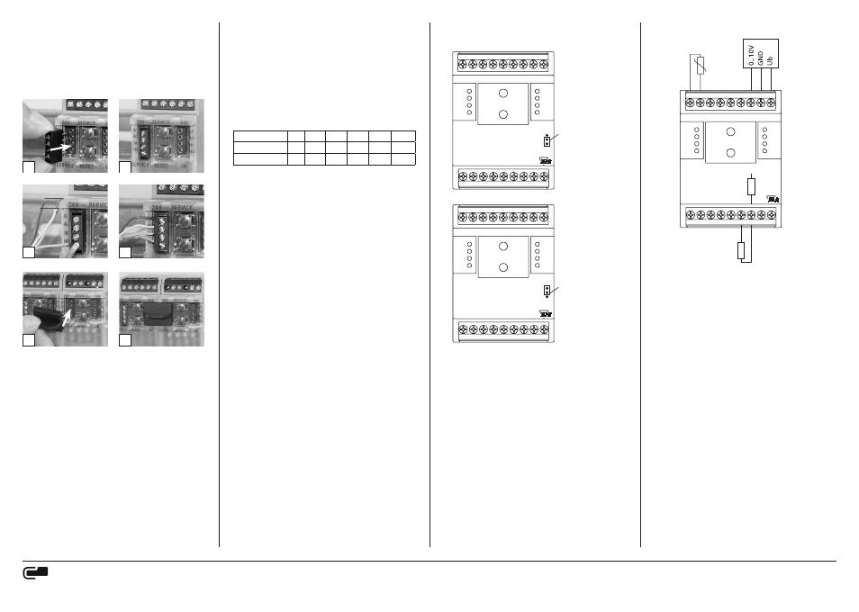
8. Jumper positions for voltage feeding
of active sensors
ERROR
24V
1
2
3
4
X10
A-
B+
GND
+24 V
24V
1 C2 2 C2 3 C2 4 C2 S
BUSY
X1
BMT-AI8
BACnet MS/TP
Jumper unter der Blende
Jumper below the faceplate
A-
B+
GND
+24 V
8 C2 7 C2 6 C2 5 C2 S
Jumper unten:
Klemmen S = 15 V DC
(Werkseinstellung)
Jumper in bottom position:
Contacts S = 15 V DC
(Facotry setting)
ERROR
24V
1
2
3
4
X10
A-
B+
GND
+24 V
24V
1 C2 2 C2 3 C2 4 C2 S
BUSY
X1
BMT-AI8
BACnet MS/TP
Jumper unter der Blende
Jumper below the faceplate
A-
B+
GND
+24 V
8 C2 7 C2 6 C2 5 C2 S
Jumper oben:
Klemmen S = 24 V AC/DC
Jumper in top position:
Contacts S = 24 V AC/DC
9. Connection examples
ERROR
24V
1
2
3
4
X10
A-
B+
GND
+24 V
24V
1 C2 2 C2 3 C2 4 C2 S
BUSY
X1
BMT-AI8
BACnet MS/TP
Passiver Fühler
Passive sensor
A-
B+
GND
+24 V
8 C2 7 C2 6 C2 5 C2 S
Pullup Widerstand
Pullup resistor
24 V
J
15 V
Halbleiter Sensor
Semiconductor sensor
Aktiver Fühler
Active sensor
7. Network adress and Bit rate setting
Configuration Switches
Hexadecimal Switches x10, x1 define the Network Address
(00 - F9; e.g. F9h = 15x16+9 = 249d) and Baud rate (FA – FF).
• Turn Switch x10 to E (Device is temporaryly configured as Slave)
• Turn Switch x1 to A – F to select Baud rate
• Turn Switch x10 to F, wait 1 second
• Red and green LEDs are blinking when Baud rate ist stored in
EEPROM
• Turn Switch x10 to select Network Address
• Turn Switch x1 to select Network Address
MS/TP Master if using Network Address 0x00 … Max_Master,
MS/TP Slave if using Network Address Max_Master + 1 … 0xF9.
Factory setting: 9600 Bit/s
Adress switch x10
F
F
F
F
F
F
Adress switch x1
A
B
C
D
E
F
Bit rate (Bit/s)
9600 19200 38400 57600 76800 115200
METZ CONNECT GmbH
Im Tal 2 | 78176 Blumberg | Germany | Phone +49 7702 533-0 | Fax +49 7702 533-433
Mounting instruction see www.metz-connect.com