8 kbps rs-422 interface (p2), Alarm outputs (tb1), A.2.3 alarm outputs (tb1) – Comtech EF Data SMS-451 User Manual
Page 57
SMS-451T 1:1 ESC Protection Switch
Revision 0
B-141-1 Interface Breakout Panel
MN/SMS451.IOM
A–5
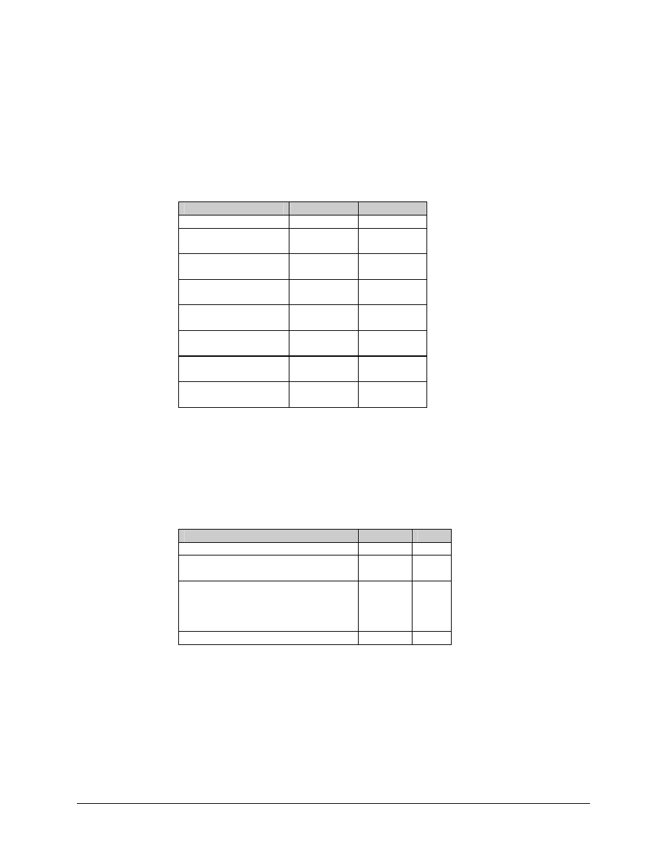
A.2.2
8 kbps RS-422 Interface (P2)
The 8 kbps RS-422 interface is provided on a 37-pin female D connector accessible from
the front of the breakout panel. Screw locks are provided for mechanical security of the
mating connector.
Signal Function
Name
Pin #
GROUND
GND
1, 19, 20, 37
1KHZ TX OCTET
TXO-A
TXO-B
3
21
8KBIT TX DATA
TXD-A
TXD-B
4
22
8KHZ TX CLOCK
TXC-A
TXC-B
5
23
8KBIT RX DATA
RXD-A
RXD-B
6
24
REQUEST TO SEND/
CLEAR TO SEND
RTS_CTSB
RTS_CTSA
25, 27
7, 9
8KHZ RX CLOCK
RXC-A
RXC-B
8
26
1KHZ RX OCTET
RXO-A
RXO-B
15
33
Note: RTS and CTS are looped together on the connector.
A.2.3
Alarm Outputs (TB1)
The alarm outputs are provided on an 8-position terminal block located on the front panel
of the breakout panel.
Signal Function
Name
Pin #
GROUND GND
1
DEMOD FAULT RELAY
DF-COM
DF-NO
2
3
BACKWARD ALARM INPUT
BWI-1
BWI-2
BWI-3
BWI-4
4
5
6
7
DEFERRED MAINTENANCE ALARM
DMA
8