5 remote port (j4) -4, 6 terminal port (j5) -4, 7 rx rf in (l-band) (j6) -4 – Comtech EF Data DD240XR Rev Е User Manual
Page 92: 8 rx if in (j7) -4
Electrical Interfaces
DD240XR High-Speed Digital Demodulator
5-4
MN-DD240XR – Rev. E
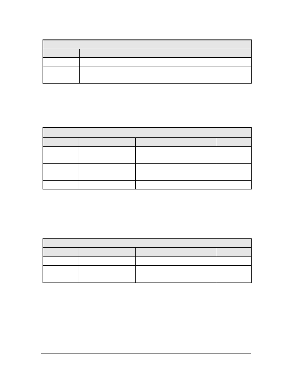
Table 5-2. Alarm Indications
Alarm
Pin Description
None
1 – 2 shorted, 7 – 8 shorted, open collector output driven low
Minor
1 – 2 shorted, 8 – 9 shorted, open collector output driven low
Major
2 – 3 shorted, 7 – 8 shorted, open collector output open
5.5 Remote Port (J4)
The Remote Port Interface (J4) can be used for the monitor & control functions of the unit. The
physical interface is a female 9-Pin D-Sub Connector. This bi-directional port complies with
RS-485 Electrical Specifications. Refer to Section 7.6 for protocol and programming details. Pin
outs are listed in Table 5-3.
Table 5-3. J4 - RS-485 Remote Control- 9-Pin ‘D’ Female
Pin No.
Signal
Description
Direction
1
Tx (B)
Transmit Data (+)
Output
5
GND
Ground
-
6
Tx (A)
Transmit Data (-)
Output
8
Rx (B)
Receive Data (+)
Input
9
Rx (A)
Receive Data (-)
Input
5.6 Terminal Port (J5)
The Terminal Port Interface (J5) can be used for the monitor & control functions of the unit. The
physical interface is a female 9-Pin D-Sub Connector. This bi-directional port complies with
RS-232 Electrical Specifications. Refer to Section 4.6 for terminal interface details. The pinouts
are listed in Table 5-4.
Table 5-4. J5 - RS-232 Terminal Port - 9-Pin ‘D’ Female
Pin No.
Signal Name
Description
Direction
3
TxD
Transmit Data
Output
2
RxD
Receive Data
Input
5
GND
Ground
---
5.7 RX RF IN (L-Band) (J6)
The Receive RF In (L-Band) (J6) Port is the L-Band input for the DD240 L-Band, 950 – 2150 MHz
tuning ra
nge through a 75Ω Female F-Type Connector.
5.8 RX IF IN (J7)
The RF Port is a 75Ω Female BNC-Type Connector, and the tuning range is 50 – 180 MHz.