Cb 5 series – Code Blue CB 5-S ECONOMICAL SLIM HELP POINT User Manual
Page 32
Code Blue
•
259 Hedcor Street
•
Holland, MI 49423 USA
•
800.205.7186
•
www.codeblue.com
GU-158-D
page 32 of 42
CB 5 Series
Administrator Guide
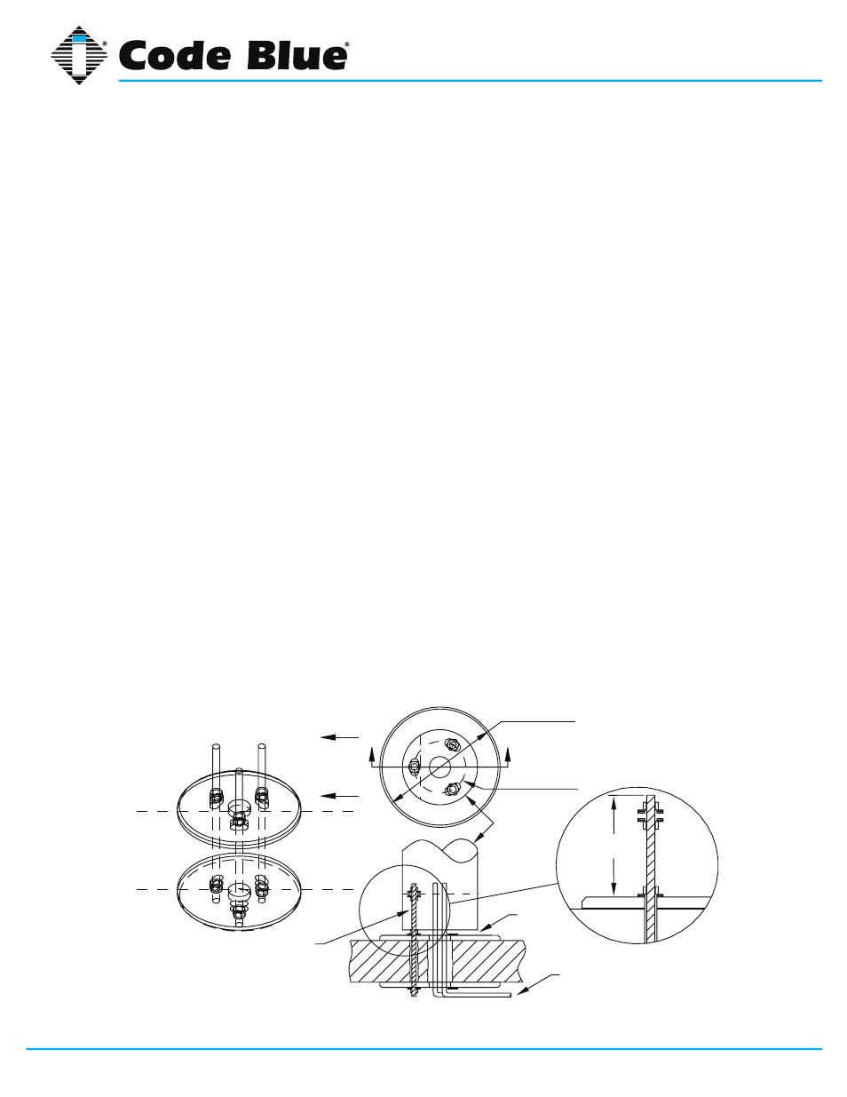
21 CB 5 Series Deck Mount Installation Instructions
1.0 DECK MOUNT FOUNDATION
1.1
Drill Deck Holes – Drill three holes through the deck or floor for the three 3/4” threaded rods.
The holes should be aligned, using the template provided, so the phone faceplate on the unit
will face in the desired direction (see figure below). Drill a fourth hole in the center to accom-
modate the conduit.
1.2
Position Upper Deck Plate – Position the first plate working from above the deck. Thread a
nut and washer on the end of each rod so that approximately six inches extends beyond the
base of the washer. Insert each rod through the top side of the plate, plate gasket, and down
through the three holes in the deck. (
NOTE: The top of the plate is the side with the tapered
edge.)
1.3
Position Lower Deck Plate – Position the second plate working from below the deck. Have
another worker hold the upper plate and rods in place from above the deck. Place the second
plate gasket and then the second plate over the threaded rods. Secure the second plate with
nuts and washers provided. If required, re-adjust the nuts so that six inches of the rods are
above the top of the upper plate. (see figure below)
1.4
Secure Lower Nuts – To prevent tampering, it is advisable to tack weld the lower nuts to the
threaded rod.
2.0 WIRING
2.1
Pull power and phone line through conduits – A minimum of two feet of wire must be avail-
able from the conduit for electrical and communications wiring.
2.2
Conduit – Electrical and telephone line conduit is run through the deck and the center open-
ings (two inch diameter) of the upper and lower deck plates. A minimum of four inches and a
maximum of six inches of conduit above the upper plate are required.
B
B
CB V Base
3/4" THREADED ROD OF SUFFICENT
LENGTH TO PASS THROUGH DECK
AND ALLOW A MINIMUM OF 6”
ABOVE THE TOP DECK PLATE.
6.00
Ø14.00
DECK PLATE
PHONE
FACEPLATE
DIRECTION
ALLOW
1/2" GAP FOR
VENTING
ELECTRICAL
AND TELEPHONE
LINE CONDUIT
Ø
6.00
BOLT CIRCLE
All wiring must be installed and connected by experienced and certified personnel to meet
local and national electrical codes, and will include a service disconnect.