Installing transformers without, Cxl series rackmount housings – Cloud Electronics CXL-100T User Manual
Page 9
CXL Manual v1.0
9
Installing transformers without
CXL Series rackmount housings
Where appropriate, CXL Series transformers may be
installed in various ways without the use of CXL-800
or CXL-1600 rackmount housings. However, it is important
to appreciate that correct use of the rackmount housings
provides good safety protection from the high voltages
involved (see “Important Safety Notes” on page 2).
If fitting the transformers without rackmount housings,
careful attention must be paid to the safety aspects of the
installation, to prevent the risk of electric shocks.
A transformer may be mounted horizontally or vertically
onto any convenient clear, flat surface with the single M6
fixing bolt through the toroid’s centre hole. Mounting it
immediately adjacent to the amplifier is not mandatory,
though may often be the most practical solution.
Consideration should be given to ventilation, particularly
if multiple transformers are housed together and/or
the amplifier has a high duty cycle (i.e., handling audio
continuously).
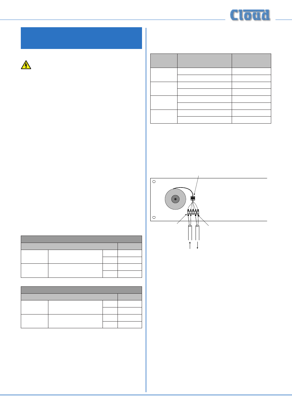
Refer to “Fitting the connectors” on page 6. The
transformer’s windings are terminated in a 2-pin (primary)
and a 3-pin (secondary) 5 mm–pitch female screw-
terminal connector mounted on a PCB. When mounting a
transformer without a rack tray, the connector assembly
should be removed by cutting it off. Connection to the
amplifier’s low-impedance output and to the loudspeaker
system can be made using insulated terminal blocks (see
Safety Notes below).
Take care to observe the wire colour coding:
100 V SYSTEMS
Connection
Colour
Primary
From amplifier’s lo-Z
output
+
Red
-
Black
Secondary
To 100 V-line loudspeak-
er system
+
White
-
Blue
70 V SYSTEMS
Connection
Colour
Primary
From amplifier’s lo-Z
output
+
Red
-
Black
Secondary
To 70 V-line loudspeaker
system
+
Purple
-
Blue
Use wire of the correct gauge for the transformer/amplifier
power rating; this applies to both primary and secondary
connections. The minimum wire gauges to be used are given
in the following table:
TYPE
CONNECTION
MIN. WIRE
GAUGE
CXL-40T
Primary (input)
1.5 mm
2
Secondary (output)
0.75 mm
2
CXL-100T
Primary (input)
1.5 mm
2
Secondary (output)
0.75 mm
2
CXL-200T
Primary (input)
1.5 mm
2
Secondary (output)
1 mm
2
CXL-400T
Primary (input)
1.5 mm
2
Secondary (output)
1 mm
2
The wiring should make use of insulated terminal blocks and
fully-shrouded crimp terminals. Where possible, secure the
terminal blocks to the panel on which the transformers are
mounted with screws or nuts and bolts as appropriate. Keep
the transformers’ leads neat with cable ties and sticky-back
bases.
If transformers are being freely-mounted on a panel within
an equipment rack, fit lockable side and rear doors, and
blank 19” panels as necessary to the rack, to prevent access
to the terminations. If the transformers are to be housed
externally to a rack, the use of a lockable IP-rated enclosure
fitted with the appropriate cable grommets is recommended.