Installing transformers in the, Cxl-1600 rackmount housing, Fitting the connectors – Cloud Electronics CXL-100T User Manual
Page 7: Re-assembling the housing, Cxl manual v1.0 7
CXL Manual v1.0
7
Installing transformers in the
CXL-1600 rackmount housing
The CXL-1600 is a fully enclosed steel 19” rackmount
housing; it has a depth of 225 mm, but a minimum rack depth
of 250 mm is recommended to allow adequate clearance for
rear connectors and cables.
Up to four CXL-200T or CXL-400T transformers may be
installed in a CXL-1600. Any mixture of the two types may
also be fitted, up to a total of four transformers. The
CXL-1600 will also accept up to CXL-40T and/or
CXL-100T transformers, in the same manner as the
CXL-800. Mixtures of all transformer types are permissible,
up to the maximum limits specified in the table in
“Transformer/Rackmount Housing compatibility” on page 5
Remove the top cover of the housing and retain the screws.
Each transformer is fitted to the chassis baseplate with
a single M6 bolt (one supplied with each transformer).
Identify the twelve pre-drilled 6 mm holes in the baseplate.
If fitting a mixture of transformer types, note that certain
constraints exist as to transformer positioning, due to the
larger diameter of the higher-powered transformers. See
the template supplied with the housing, which illustrates the
locating options. Note that when fitting four CXL-200T and/
or CXL-400T transformers, only the four odd-numbered
positions are available as combinations. Specific baseplate
holes are provided to cater for these transformer types.
When each transformer position has been determined,
insert the bolt from the underside of the chassis, place
the transformer in position with the bolt through the
central hole, and secure it in place with the washer
and locknut supplied. Before final tightening, rotate
the toroids to ensure that the cable assemblies
for all the transformers emerge from the windings
at a neat orientation for wiring to the rear panel.
If the CXL-1600 is being fitted with less than its full
complement of transformers, any positions may be used
as convenient, provided the spacing constraints of mixed
transformer sizes are observed.
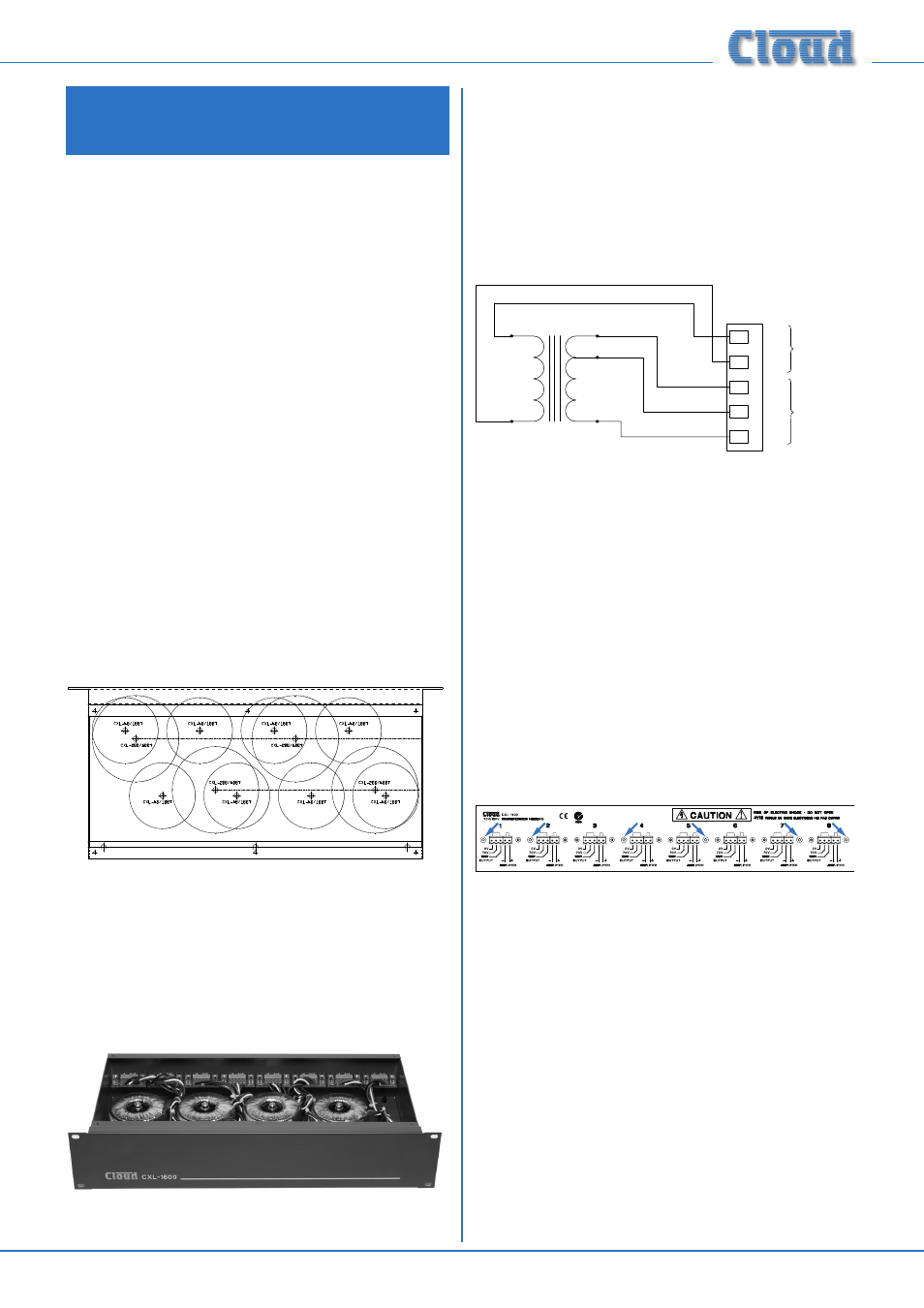
Fitting the connectors
Note that each of the transformer positions is aligned with
one of the rear panel connector positions.
Each transformer has five colour-coded wires which
terminate on a small PCB. A 2-way and a 3-way 5 mm-pitch
female connector, and two M3 fixing brackets are fitted to
the PCB. Locate the connectors into the rectangular rear
panel slot which is in line with the transformer’s position.
Note that, looking at the rear panel, the 3-way connector
goes to the left of the slot.
Secure each PCB/connector assembly in place with EITHER
two M3 x 6 mm Pozi screws, OR one M3 x 6 mm Pozi screw
and one M3 x 25 mm hex pillar. The screws and/or pillars
should be passed through the fixing holes and tightened into
the tapped holes in the fixing brackets. Which of the two
fixing options is used depends on the connector (from 1 to
8) being fitted. The diagram below shows a rear panel with
all eight connectors fitted; the arrows indicate the correct
locations for the hex pillars.
See diagram on page 6 for details of connector
mountings
IMPORTANT: If less than eight transformers are installed in
the rackmount housing, it is still important to fit all six hex
pillars (supplied) in the positions indicated. If a connector
position requiring a hex pillar is empty (due there being no
transformer in that position), use an M3 shakeproof washer
and nut (supplied) to secure the hex pillar in place.
Re-assembling the housing
Replace the lid of the housing and secure using the original
screws.