Installing transformers in the, Cxl-800 rackmount housing, Fitting the connectors – Cloud Electronics CXL-100T User Manual
Page 6: Re-assembling the housing, Cxl manual v1.0 6
CXL Manual v1.0
6
Installing transformers in the
CXL-800 rackmount housing
The CXL-800 is a steel 19” rackmount tray of open
construction; it has a depth of 225 mm, but a minimum
rack depth of 250 mm is recommended to allow adequate
clearance for rear connectors and cables.
Up to eight CXL-40T or CXL-100T transformers may be
installed in a CXL-800. Any mixture of the two types may
also be fitted, up to a total of eight transformers.
The CXL-800 is not designed for CXL-200T or CXL-400T
transformers. These types should only be fitted into the
CXL-1600 rackmount housing.
Each transformer is fitted to the chassis baseplate with
a single M6 bolt (one supplied with each transformer).
Identify the eight pre-drilled 6 mm holes in the baseplate
(in two rows of four); insert the bolt from the underside
of the chassis, place the transformer in position with the
bolt through the central hole, and secure in place with the
washer and locknut supplied. Before final tightening, rotate
the toroids to ensure that the cable assemblies for all the
transformers emerge from the windings at a neat orientation
for wiring to the rear panel.
If the CXL-800 is being fitted with less than its full
complement of transformers, they may be mounted in any
of the positions, as convenient. Spacing them across the
width of the baseplate to give a good mechanical balance is
generally sensible.
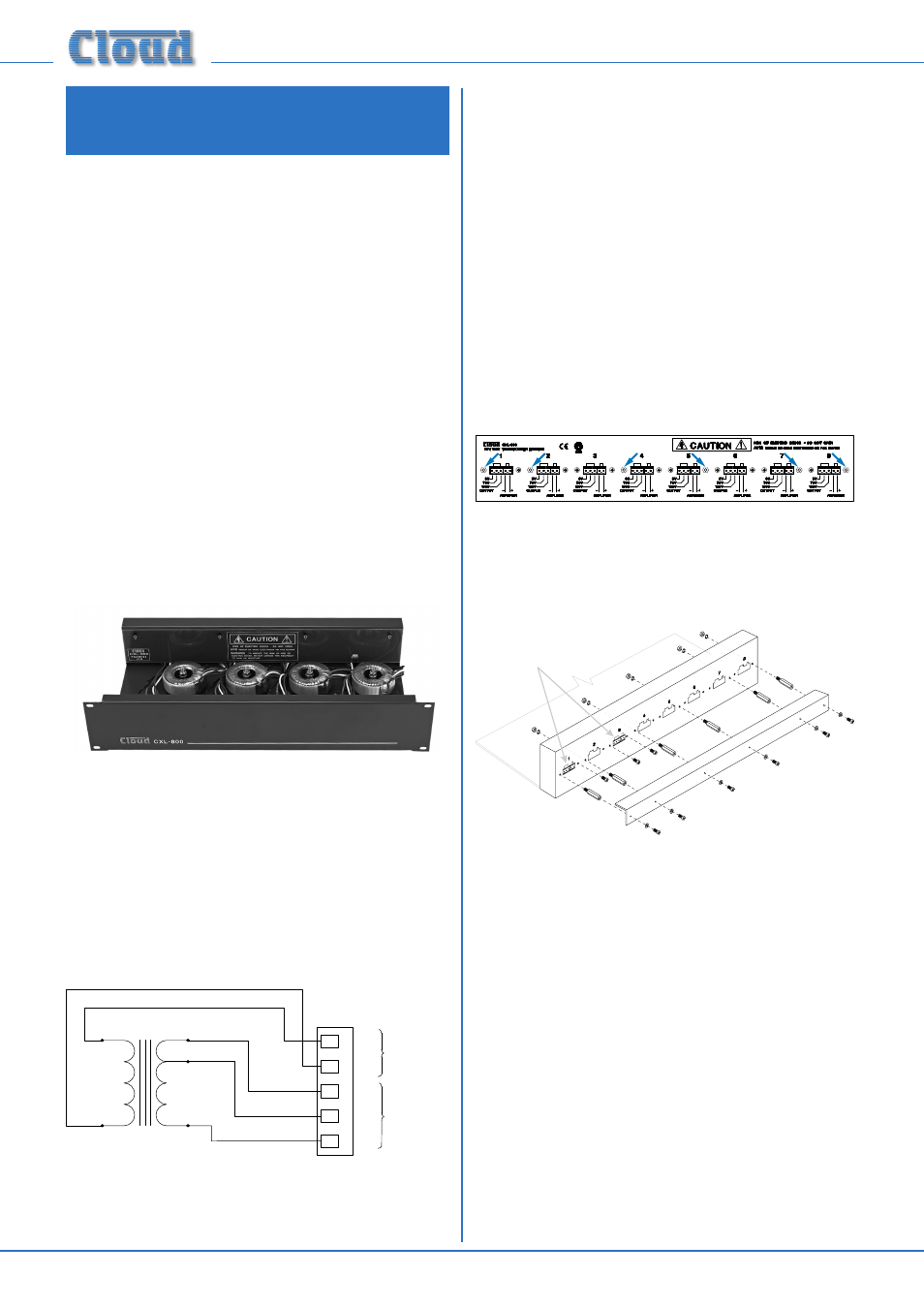
Fitting the connectors
Note that each of the transformer positions is aligned with
one of the rear panel connector positions.
Each transformer has five colour-coded wires which
terminate on a small PCB. A 2-way and a 3-way 5 mm-pitch
female connector and two M3 fixing brackets are fitted to
the PCB. Locate the connectors into the rectangular rear
panel slot which is in line with the transformer’s position.
Note that, looking at the rear panel, the 3-way connector
goes to the left of the slot.
Secure each PCB/connector assembly in place with EITHER
two M3 x 6 mm Pozi screws, OR one M3 x 6 mm Pozi screw
and one M3 x 25 mm hex pillar. The screws and/or pillars
should be passed through the fixing holes and tightened into
the tapped holes in the fixing brackets. Which of the two
fixing options is used depends on the connector (from 1 to
8) being fitted. The diagram below shows a rear panel with
all eight connectors fitted; the arrows indicate the correct
locations for the hex pillars.
Transformer
Connectors
IMPORTANT: If less than eight transformers are installed
in the rackmount housing, it is still important to fit all
six hex pillars (supplied) in the positions indicated. If a
connector position requiring a hex pillar is empty (due there
being no transformer in that position), use an M3 shakeproof
washer and nut (supplied) to secure the hex pillar in place.
Re-assembling the housing
Tidy the transformer wires inside the housing so that
they follow the base of the chassis. Fit the fibreglass safety
cover (Part No. PC340144) inside the rear panel so that
the transformer wires pass under it and it covers the rear
connectors. Note the four fixing holes (arrowed) should be
uppermost. Screw the cover to the folded rear panel flange
with four of M3 x 6 mm Pozi screws.