Connecting and mounting – cdr-1f – Cloud Electronics CDR-1B User Manual
Page 13
CDR‑1 & CDR‑1F Installation Guide v2.0
13
Connecting and mounting – CDR-1F
The CDR-1F is intended for use with dual-gang UK size steel or PVC dry-lining back
boxes with an internal depth of 47 mm. As the internal electronic assembly is fully
screened, It can also be mounted without a back box directly into a suitable wall cavity.
Refer to page 14 for CDR-1F dimensions
In order for the display to be readily legible, only “landscape” orientation should be
employed.
1.
With back box: bring the CAT-5 cable(s) into the back box. If a local external
PSU is being used to power the CDR-1F, the feed from this should be fed through
as well.
Without back box: simply feed the cables up through the hole in the wall.
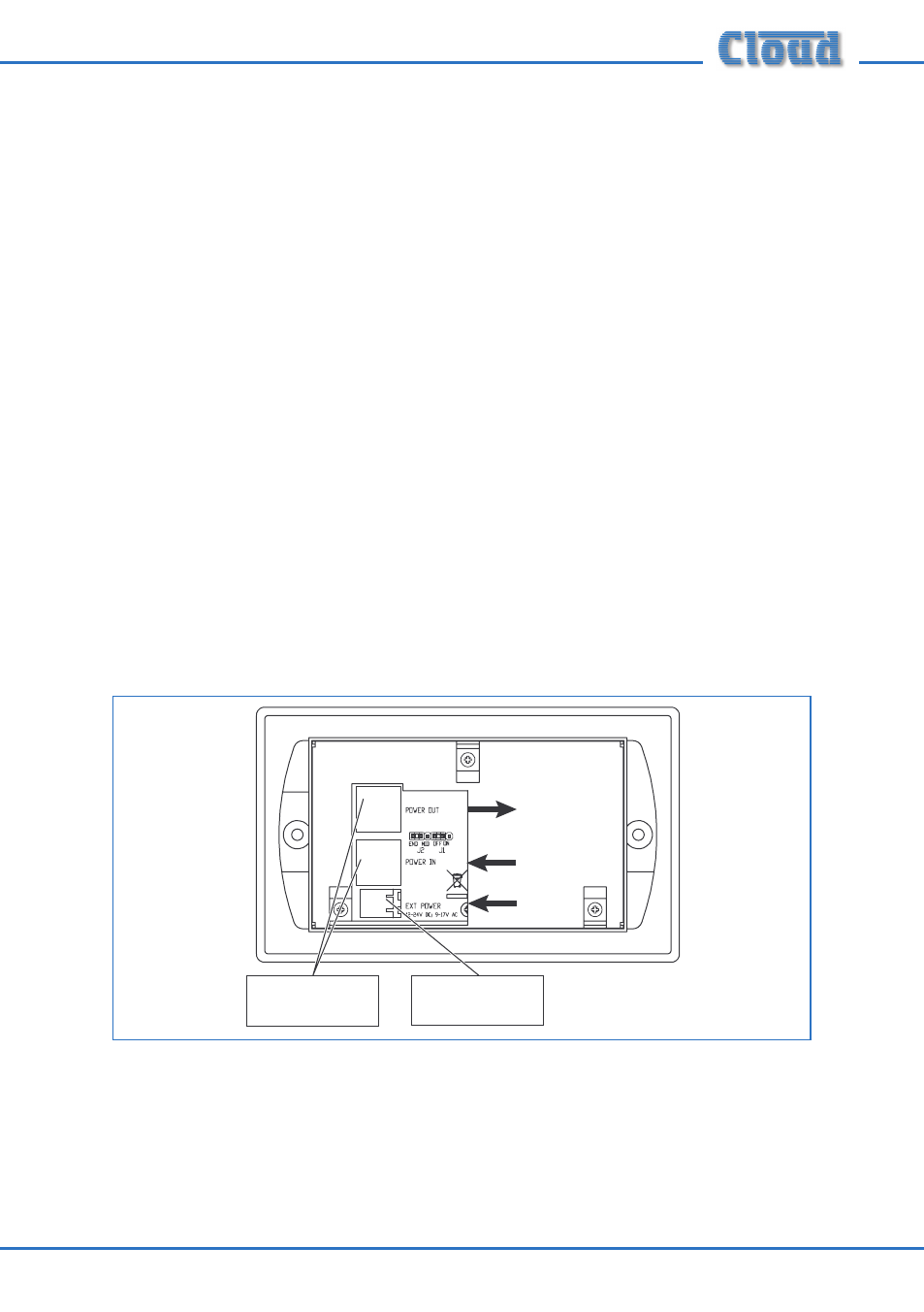
2. Plug the cables into the CDR-1F sockets. The CAT-5 cable going to the mixer
(possibly via other CDRs) should be connected to the POWER IN socket. If other
CDRs are being installed further along the chain, the outgoing cable should be
connected to the POWER OUT socket. Ensure the RJ45 connectors fully latch
into place. If an external PSU is being used, plug it into the 2-pin EXT POWER
socket.
RJ45 SOCKETS FOR
DATA
INTERCONNECTION
2-PIN EXTERNAL
POWER SOCKET
TO NEXT CDR
FROM DCM-1/e