Cloud Electronics CDR-1B User Manual
Page 11
CDR‑1 & CDR‑1F Installation Guide v2.0
11
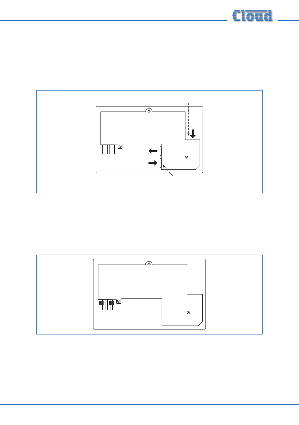
4. Plug the cables into the CDR-1 sockets. The CAT-5 cable going to the mixer
(possibly via other CDRs) should be connected to the POWER IN socket. If other
CDRs are being installed further along the chain, the outgoing cable should be
connected to the POWER OUT socket. Ensure the RJ45 connectors fully latch
into place. If an external PSU is being used, plug it into the co-axial EXT POWER
socket.
J2
J1
MI
D
EN
D
ON
OF
F
POWER
OUT
POWER
IN
FROM
DCM-1
EXT POWER
RJ45 SOCKETS FOR
DATA
INTERCONNECTION
CO-AXIAL SOCKET
FOR EXTERNAL PSU
TO NEXT
CDR-1
5. Check that jumper J1 is in the OFF position. J2 should be set according to the
CDR-1’s position in the CAT-5 “chain”. If it is the final (or only) panel in the chain
(i.e., nothing is plugged into the POWER OUT connector), set J2 to END; in all
other cases set it to MID. Carefully use tweezers or a pair of fine-nosed pliers for
this operation.
J2
J1
MI
D
EN
D
ON OF
F