Output wiring – Cloud Electronics 46-50 - CXL-4160 User Manual
Page 5
CXL-4160 Installation Instructions v1.0
5
OUTPUT WIRING
The cable used for the 70/100 V-line system must be 0.75mm² or more, double insulated and be capable of carrying at least 1 A
rms
.
When long distances are involved, it may be advantageous to use cable with a higher cross-section.
CHANGING THE CXL-4160 BETWEEN
100 V-LINE AND 70 V-LINE OPERATION
The secondary windings of the transformers used in the CXL-4160 module are tapped at 70 V and 100 V. The module will be
supplied pre-configured for the voltage normally used in your territory. To use the 46-50 with the “alternative” line system voltage,
the tapping must be changed. This is done by moving soldered wire links on the rear of the module PCB. There is one link for each
transformer.
NOTE: This operation should only be performed by someone experienced in PCB soldering.
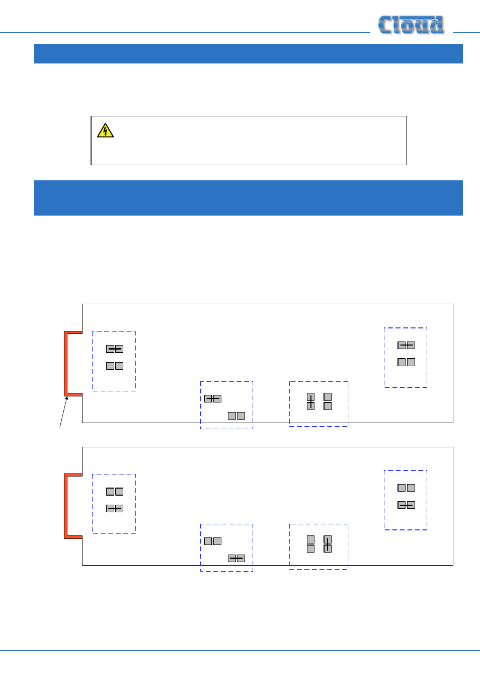
The diagram below indicates the location of the solder links for each transformer:
SOLDER SIDE OF PCB, SHOWING APPROX. LOCATIONS OF WIRE LINKS
OUTPUT CONNECTOR
100 V
70 V
ZONE 2
100 V
70 V
ZONE 1
100
V
70
V
ZONE 3
100 V
70 V
ZONE 4
Transformers configured for 100 V-line operation
Transformers configured for 70 V-line operation
100 V
70 V
ZONE 2
100 V
70 V
ZONE 1
10
0
V
70
V
ZONE 3
100 V
70 V
ZONE 4
Transformers configured for 70 V-line operation
Unsolder the links from their existing pairs of pads and re-solder them to the other pair. A desoldering tool may be helpful in
removing excess solder. Take care not to make any accidental solder “bridges” between other pads.
The 46-50’s low-impedance outputs remain active after the CXL-4160 has been
installed, but should NOT have a load connected to them while the 70/100 V-line
outputs are in use.