Cloud Electronics 46-50 - CXL-4160 User Manual
Page 3
CXL-4160 Installation Instructions v1.0
3
Proceed as follows:
1. Disconnect the 46-50 from the mains. If it is fitted in a rack, disconnect all inputs and outputs and remove it from the rack.
Orientate the unit with the rear nearest to you. Remove the top cover; retain the eight fixing screws.
2. Remove the blanking plate from the
100V/70V LINE OUTPUTS connector location on the rear panel; retain the plate and
screws, nuts and washers.
3. Identify the eight empty M3 holes on the right-hand side of the 46-50’s enclosure (as viewed from the rear). The CXL-4160
module is fixed using these holes and the eight hex spacers fitted to the rear of the PCB. Align the spacers with the holes, and
fix with the eight black M3 screws supplied. The output connector should protrude neatly through the punch-out vacated in
Step 2.
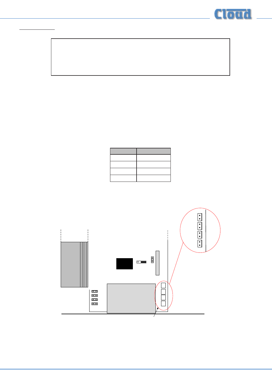
4. Fit the supplied cable assembly: the 8-pin header on the CXL-4160 PCB is connected to the four 2-pin headers on the 46-50
main PCB, located immediately behind the
100V/70V OUTPUTS connector location - see below. Note that the wire pairs
are colour coded for clarity:
ZONE
PAIR COLOUR
ZONE 1
Mauve
ZONE 2
Grey
ZONE 3
Blue
ZONE 4
Black
Note that any or all of the four channels may be converted as required.
MAIN PCB
CON 8
Connectors for CXL4160 transformer
assy.
REAR PANEL
ZONE 1
ZONE 2
ZONE 3
ZONE 4
MAINS INPUT SUB-BOARD
IMPORTANT: The CXL-4160 is preset at the factory for either 100 V-line or 70 V-line
operation, according to territory. The relevant voltage is clearly indicated on the label on the
outside of the box.
If the alternative operating voltage is needed, refer first to the manual section “Changing the
CXL-4160 between and 100 V-line and 70 V-line operation”.