Zone 1 output, Zone 2 output, Zone 3 output – Cloud Electronics 46-50 - CXL-4160 User Manual
Page 4: Zone 4 output
CXL-4160 Installation Instructions v1.0
4
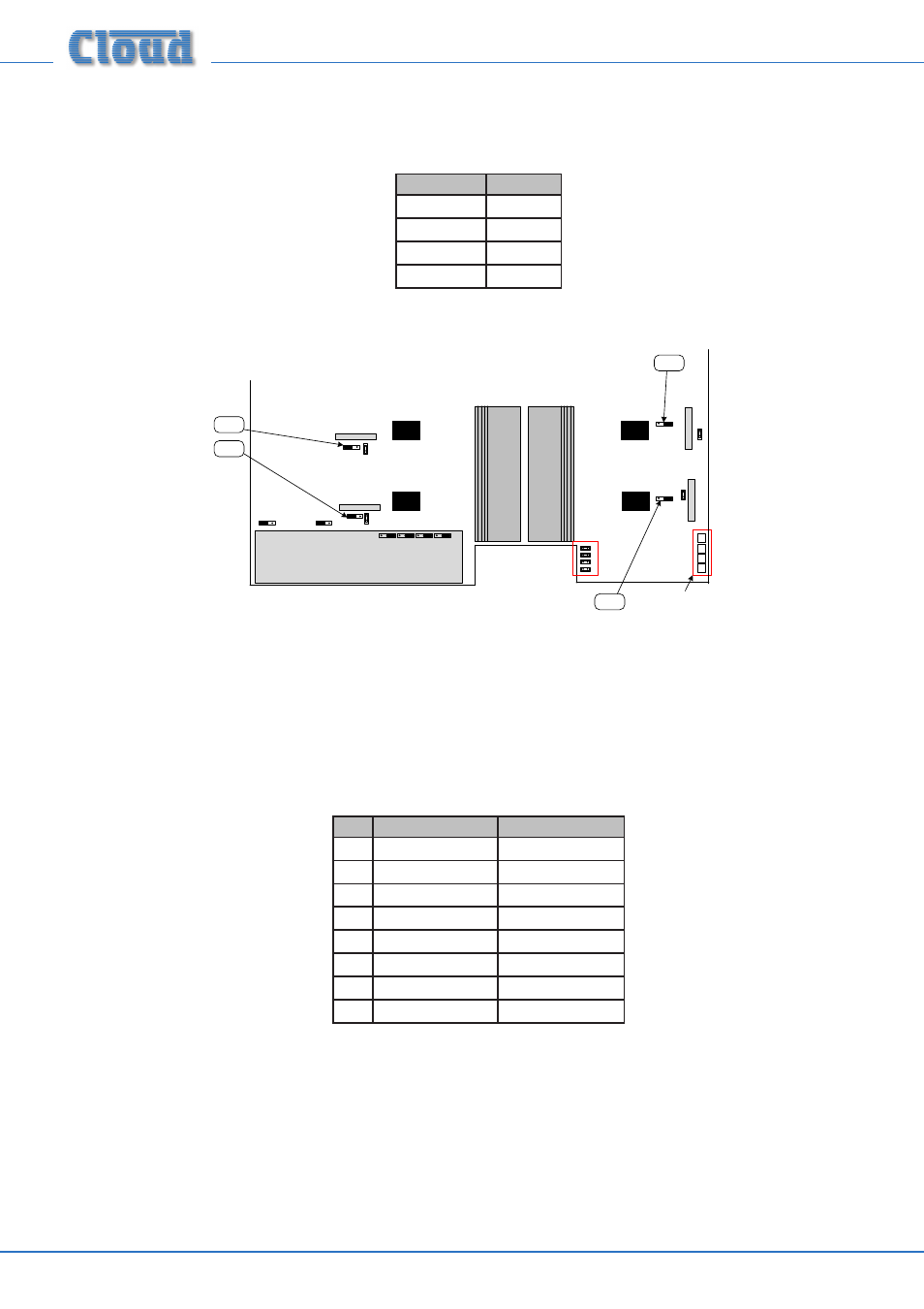
5. On the 46-50’s main PCB, enable the 65 Hz high-pass filters for the relevant channels. This is important, as low frequency
signals at high level can saturate the transformer cores, causing unpleasant distortion and possibly activating the amplifier’s
limiter circuitry. The jumpers are as follows:
OUTPUT
JUMPER
ZONE 1
J7
ZONE 2
J9
ZONE 3
J16
ZONE 4
J18
The approximate locations of the jumpers are shown in the illustration below.
LINE INPUT SUB-BOARD
J18
J16
J7
J9
CON 3
CON 4
CON 7
CON 8
Connectors for
CXL4160 transformer
assy.
NOT TO SCALE – ONLY PRIMARY
COMPONENTS SHOWN
46-50 Jumper locations.
6. Fit the two hex spacers supplied in the kit into the holes vacated in Step 2, using the same screws, nuts and washers.
7. Replace the 46-50 top cover, and reinstall in the rack (If necessary); reconnect all inputs and outputs.
8. Connect the 70/100 V-line loudspeaker system to the rear connector (see section: “Output wiring”) according to the table
below:
PANEL MARKING
CONNECT TO:
1
Z1+
Zone 1 output ‘+‘
2
Z1-
Zone 1 output ‘-‘
3
Z2+
Zone 2 output ‘+‘
4
Z2-
Zone 2 output ‘-‘
5
Z3+
Zone 3 output ‘+‘
6
Z3-
Zone 3 output ‘-‘
7
Z4+
Zone 4 output ‘+‘
8
Z4-
Zone 4 output ‘-‘
9. Fit the blanking plate from Step 2 onto the hex spacers (Step 6) over the connector using the bright M3 screws, with the
printed warnings outwards.
10. The 46-50 may now be reconnected to the AC mains and re-powered.