Delta A18657 User Manual
Page 11
11 -
English
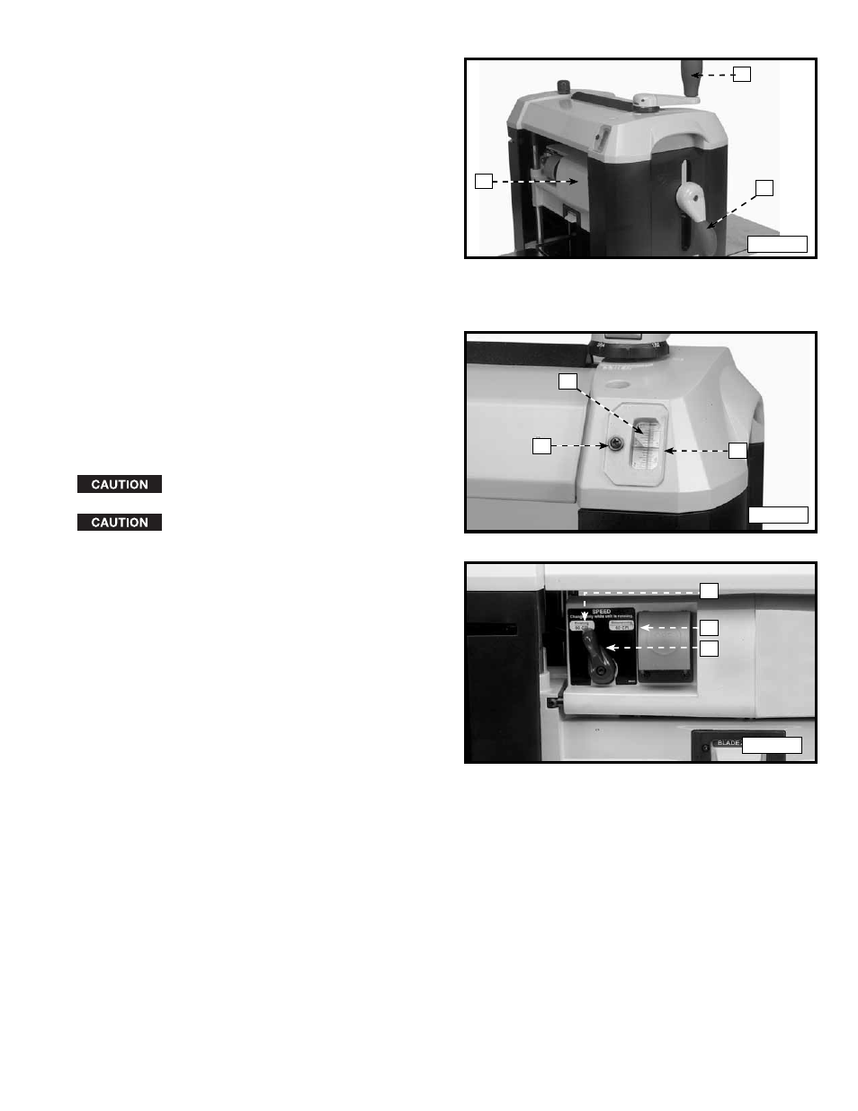
ADJUSTING THE HEAD ASSEMBLY
The head assembly (A) Fig. 12 contains the cutterhead,
Fig. 12
A
C
B
feed rollers, chip deflector and motor. Raising and
lowering the head assembly (A) controls the depth of
cut. To adjust the head assembly, rotate the cutterhead
lock handle (B) counterclockwise to unlock the
cutterhead. Turn the cutterhead adjusting handle (C)
clockwise to raise or counterclockwise to lower the
cutterhead (A). One revolution of handle (C) will move the
cutterhead up or down 1/16" (1.6 mm).
CUTTERHEAD LOCK
The cutterhead lock helps to eliminate snipe in the board
that is being planed. Snipe can also be eliminated by
butting boards end to end and feeding them through the
planer. Long boards should always be supported, when
feeding them through the planer to help eliminate snipe.
SCALE AND POINTER
A dual English/Metric scale (D) Fig. 13 and pointer (E) is
Fig. 13
F
E
D
located on the front of the machine. This scale indicates
the thickness of the finished workpiece. To adjust the
pointer (E), plane a piece of wood through the machine.
Measure the thickness of the workpiece. If an adjustment
is necessary, loosen the screw (F) and adjust the
pointer (E). Tighten the screw (F).
SPEED CONTROL
Change speeds only while the motor is
running. Do not change speeds while planing.
Make sure that the speed control is fully
engaged before feeding work material.
1. The 22-580 is a two-speed planer. The speed
Fig. 14
A
C
B
control knob (A) is shown in Fig. 14.
2. Use the “Dimensioning” speed (B) Fig. 14 with 60
cuts per inch to size the board.
3. Use the “Finishing” speed (C) Fig. 14 with 90 cuts
per inch to finish your workpiece.