7 single m16, rm16 system connections, 8 multiple m16, rm16 system connections, Single m16, rm16 system connections -4 – Cadac M16 User Manual
Page 28: Multiple m16, rm16 system connections -4
4-4
M16 Microphone Amplifier
Revision MA2005-7
4.7
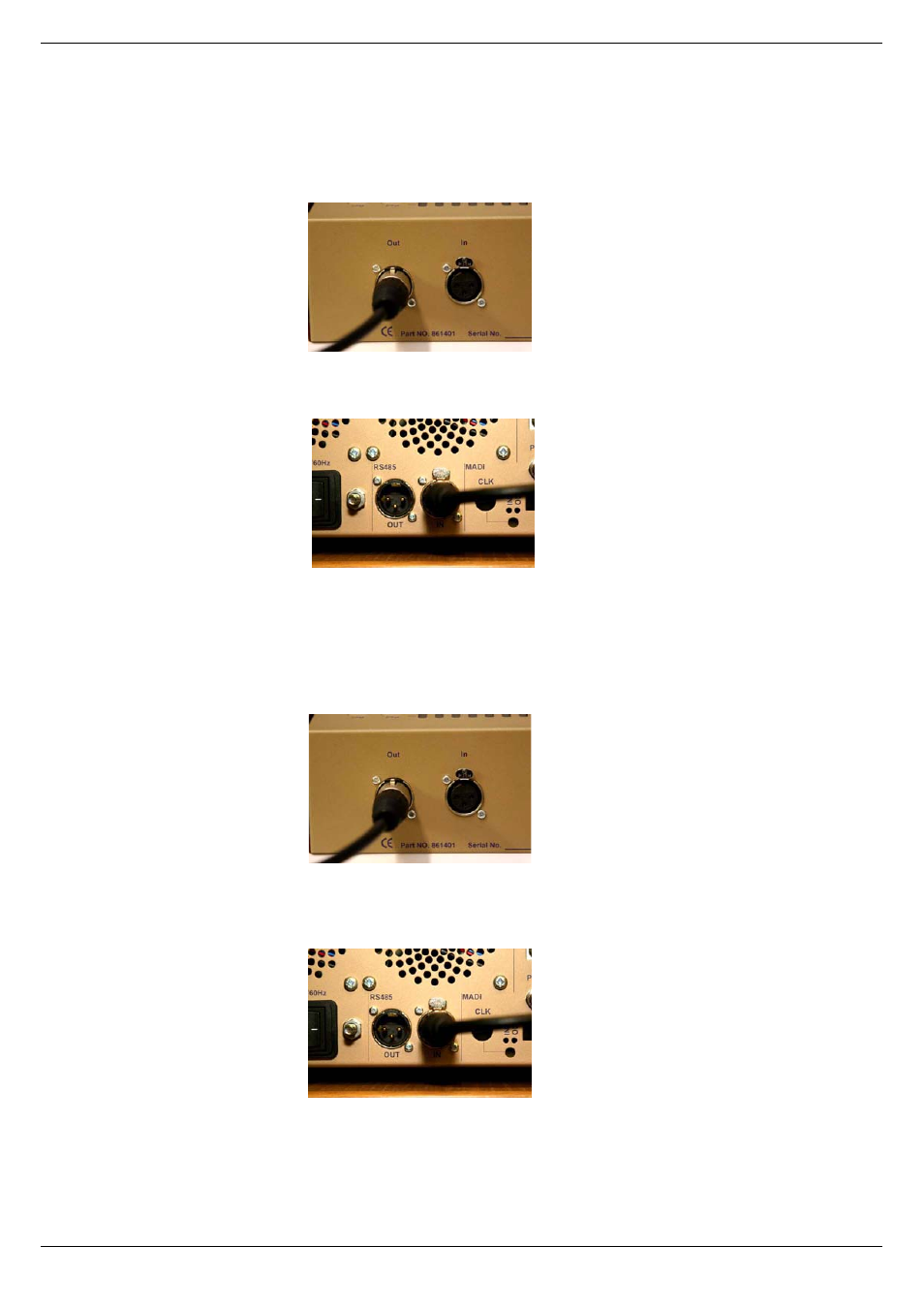
Single M16, RM16 System Connections
Using 100 ohm digital audio cable, connect one end to the OUT
XLR-3M connector located on the rear panel of the RM16.
Connect the other end of the communications cable into the RS-485
IN XLR-3F connector located on the rear panel of the M16.
4.8
Multiple M16, RM16 System Connections
Using a 100 ohm digital audio cable, terminated with XLR-3 connec-
tors, connect one end to the OUT XLR-3M connector, located on the
rear panel of the RM16.
Connect the other end of the communications cable into the RS-485
IN XLR-3F connector located on the rear panel of the first M16 of the
system. Any M16 can be assigned to be the first in the chain.
It is then a simple process of daisy-chaining additional M16s or
RM16 controllers together, by connecting RS-485 OUT XLR-3M of
M16 #1 to RS-485 IN of M16 #2 etc. Maximum configuration of a sin-
gle system is 32 x M16 and 4 x RM16 devices.
FIG 4-3. Rear panel of RM16
FIG 4-4. Rear panel of M16
FIG 4-5. Rear panel of RM16
FIG 4-6. Rear panel of M16