Cabasse ZEF 13 - ZEF 13 TR User Manual
Page 10
e n g l i s h
CONNECTION
Cable section
To get the full sonic potential of Cabasse loudspeakers and avoid
over 15% power losses, the cables connecting the speakers to the
power amplifier must have the lowest possible electrical resis-
tance. Follow the here-under diagrams to select the minimum
correct cable gauge for your high impedance installation.
Phase
In order to maintain the phase relationship and frequency balance
of the loudspeaker system, both loudspeakers must be properly
connected to the power amplifier. When properly connected, the
cones of the drivers of both loudspeakers will move in the same
direction when driven by identical signals. If the cones move in
opposite directions, the resulting out of phase signals will create
a perceptible power loss, particularly in the low frequencies. The
stereophonic message will also be degraded.Amplifier and spea-
ker manufacturers typically indicate connection polarity in one of
two ways: red and black or plus and minus. In either case, always
connect red or plus to red or plus and black or minus to black
or minus. Connections should be identical for both channels. To
check that the speakers are in correct phase, switch the system to
mono while music is being played. if the amplifier does not have
a phase inversion switch, it will be necessary to change over the
connections on one only of the loudspeakers. If in correct phase,
the image should be distinctly located between the loudspeakers
with a slight loss of bass and low midrange level. If the image is
confused and not centrally located and there is a drastic loss of
bass and low midrange level, recheck your connections.
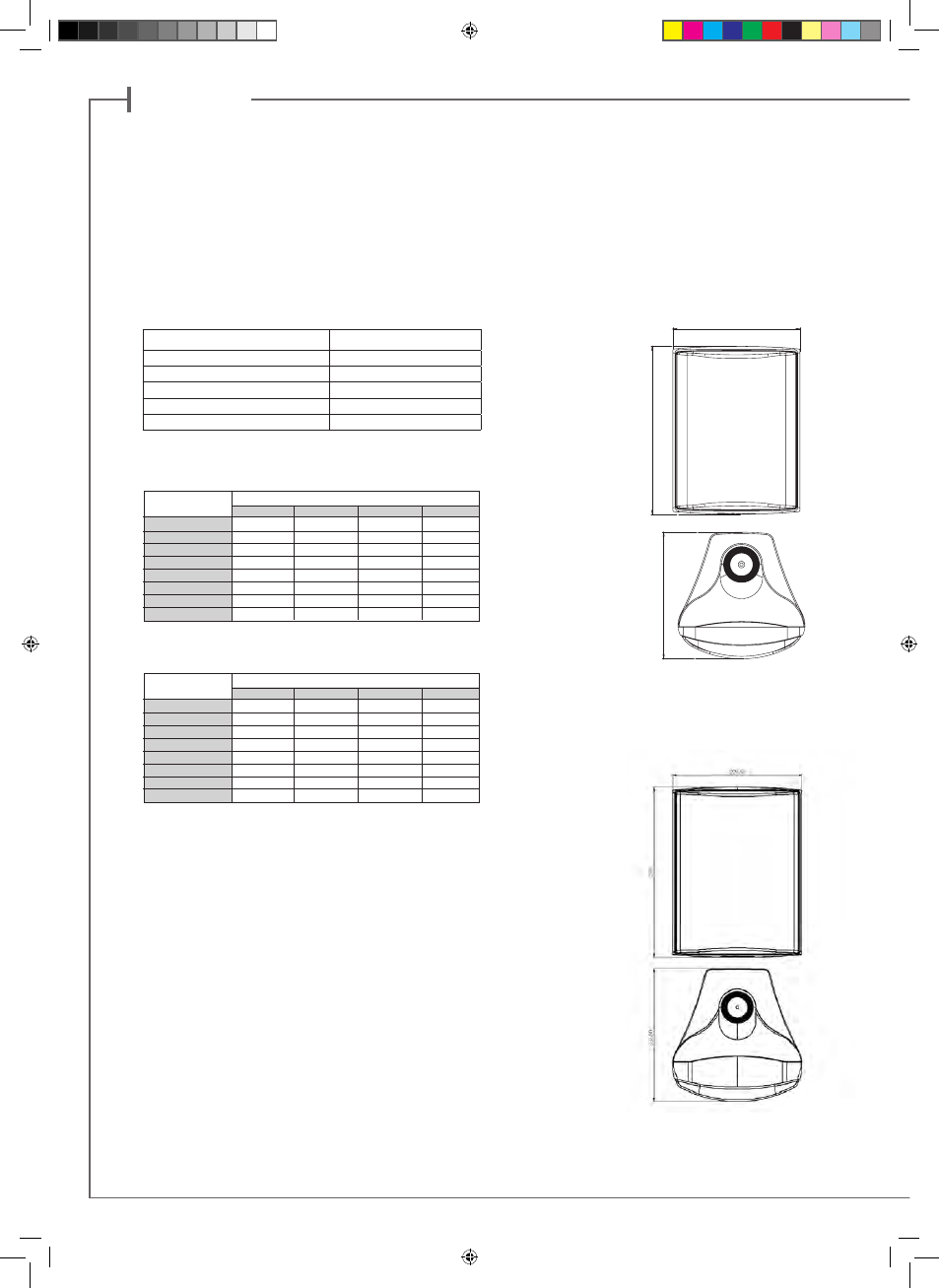
ZEF 13 - ZEF 13 TR
195
258
194
195
258
194
ZEF 17 - ZEF 17 TR
Max amp-speaker Distance
Cable Section
4.5 m
1.5 mm
2
6 m
2 mm
2
7.5 m
2.5 mm
2
9 m
3 mm
2
12 m
4 mm
2
Cable length/section for 4 ohms versions
(One speaker per amplifier output)
Length (m)
Power (W)
30 60 120 240
20
0.75mm² 0.75mm² 0.75mm² 0.75mm²
50
0.75mm² 0.75mm² 0.75mm² 0.75mm²
100
0.75mm² 0,75mm² 0.75mm² 1mm²
200
0.75mm² 0.75mm² 1mm² 1.5mm²
400
0.75mm² 1mm² 1.5mm² 2mm²
600
1mm² 1.5mm² 2mm² 2.5mm²
800
1mm² 1.5mm² 2mm² 3mm²
1000
1.5mm² 2mm² 2.5mm² 4mm²
Maximum LS cable length for 100 V mode
Length (m)
Power (W)
30 60 120 240
20
0.75mm² 0.75mm² 0.75mm² 0.75mm²
50
0.75mm² 0.75mm² 0.75mm² 1mm²
100
0.75mm² 0.75mm² 1mm² 1.5mm²
200
0.75mm² 1mm² 1.5mm² 2mm²
400
1mm² 1.5mm² 2mm² 3mm²
600
1.5mm² 2mm² 2.5mm² 4mm²
800
1.5mm² 2mm² 3mm² 4mm²
1000
2mm² 2.5mm² 4mm² 6mm²
Maximum LS cable length for 70 V mode
CAB Notice ZEF 13-17-TR.indd 10
21/03/13 17:56