6 in-line filter, 7 fluid connections, 8 electrical connections – Bronkhorst CEM W-300B User Manual
Page 9
BRONKHORST HIGH-TECH B.V.
2.6 In-line filter
Although fluids and piping should be absolutely free from dirt, it is recommended to install inline filters
upstream of the flowmeter(s).
2.7 Fluid connections
The liquid meter should be installed according to its manual. The outlet of this meter should be connected to
the liquid input port of the CEM valve. The controller section of the liquid flowmeter controls the CEM valve.
Electrical connections should be made according to the customer system description.
The outlet of the gas flow controller must be connected to the gas input part of the CEM valve.
The vapour outlet of the CEM should be directly coupled to the process, this tube should be heated at a
temperature higher than the heater in order to assure that the vapour will not condense in this line. Avoid
“cold spots” in the outlet.
* Note: Always check your system for leaks, before applying fluid pressure. Especially if toxic, explosive or
other dangerous fluids are used.
2.8 Electrical connections
2.8.1 General
Bronkhorst HIGH-TECH B.V. recommends using their standard Readout and Control module and standard
cables, which have been tested together with the system. These cables are always supplied with the CEM
system.
When not using the standard Readout and Control unit please read chapter 4.
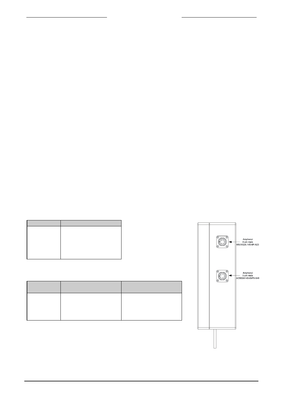
2.8.2 Pin configuration
The heat exchanger is equipped with two connectors:
connector (1) 6-pin male
Pinnumber
Description
A
B
C
D
E
F
Not connected
Not connected
PT100 (T-sensor)
PT100 (T-sensor)
Safety switch
Safety switch
connector (2) 5-pin male
Pinnumber
Description
110…120Vac supply
Description
220…240Vac supply
A
B
C
D
E
PE
Heater (N)
Heater (L)
Heater (L)
Heater (N)
PE
Not connected
Heater (N)
Heater (L)
Not connected
9.17.082
page 9