2 cabling and connectors, 1 audio cable connection, Figure 2-2 audio connection – Broadata Communications 6100E Series User Manual
Page 8
BCI 6100E User’s Manual
Digital Fiber Optic Multi-Channel Audio Transport System with Data Options
Broadata Technical Support, [email protected]
9
15
13
16
15
14
11
9
10
11
12
12
7
5
5
8
7
6
3
1
4
2
3
1
PW
R
61
00
E-T
6100E-T
4
2
9
10
13
8
6
14
16
C
H
A
N
N
E
LS
--
+
+
-
-
I N P U T S
+
-
-
-
+
-
A U D I O
RX
TX
To 6100E-R Unit
6100E-T
Unit
Audio Cable with
Terminal Block
Connector
Audio Cable with
Terminal Block
Connector
One Level
Audio Receiver
One Fiber
Cable
2.2 Cabling and Connectors
In order to setup the BCI 6100E properly, make sure to observe
the following instructions when installing the proper cables. The
6100E requires two parts to the cabling setup: the audio and
the optical.
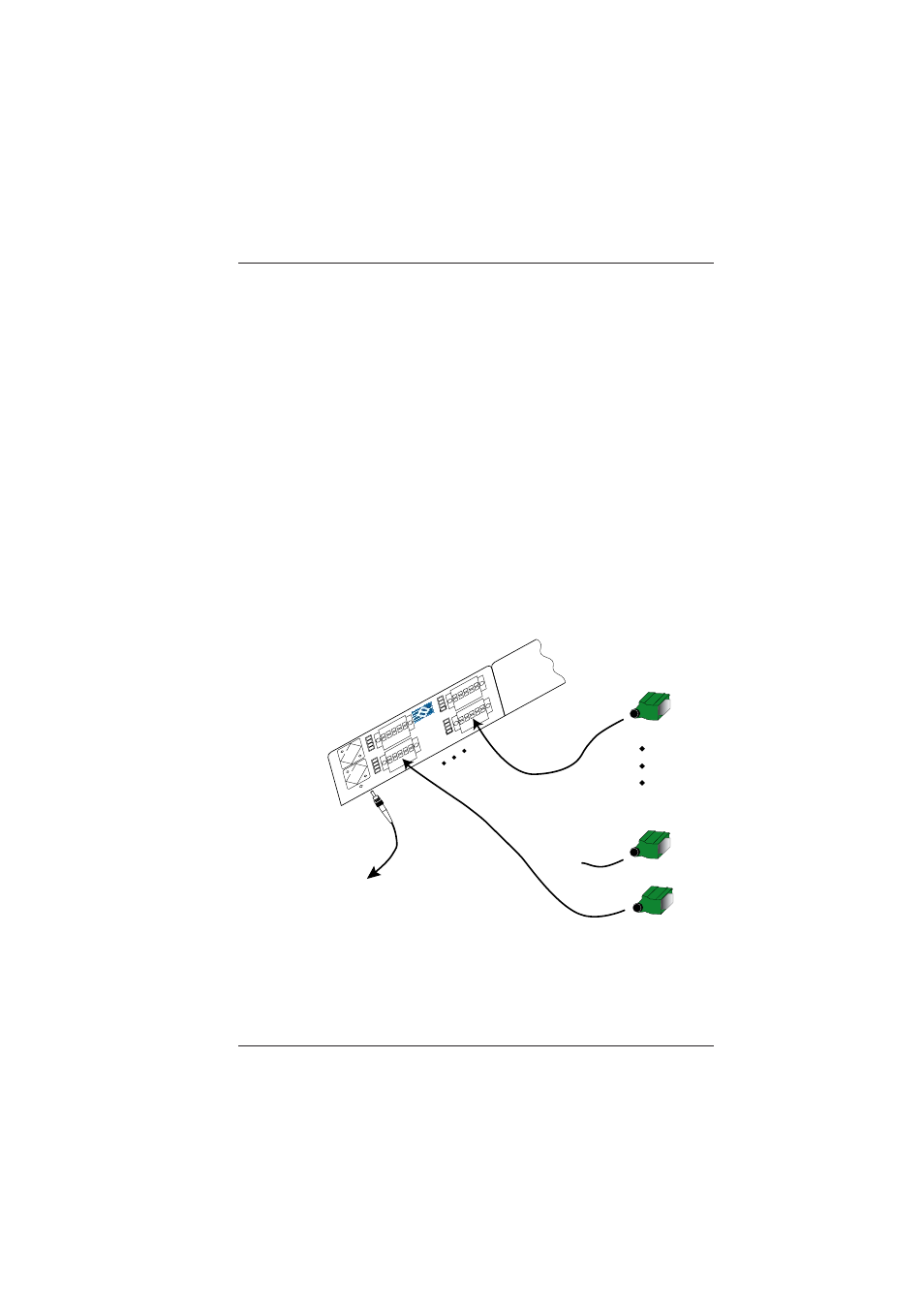
2.2.1 Audio Cable Connection
The only cable connections on the electrical side are for
the terminal block audio interfaces.
To connect the audio component, connect your terminal
block connectors to the appropriate channels, as illustrated
in Figure 2-2. The pinout assignment for the terminial block
connector is shown in Figure 2-3.
Figure 2-2
Audio Connection