Broadata Communications LBC-H/V-T-WP User Manual
Page 14
LBC-H/V-T-WP User’s Manual
Link Bridge
TM
HDMI/VGA Wall Plate Transmitter System
Broadata Technical Support, [email protected]
15
4.1 In-Wall Power/CAT-5e/6 Wiring Instruction
The in-wall power/CAT-5e/6 installation for the LBC-H/V-T-WP
wall plate must confirm national and local electrical codes, e.g.,
UL junction boxes shall be used and DC power source shall not
exceed product rated range (+24VDC @ 1A). Follow the
following steps for power/CAT5e/6 installation:
1.
Feed both CAT-5e/6 and power cables through the opening
of the wall box, and secure the cables with cable clamps
to provide strain relief.
2.
Terminated CAT-5e/6 with RJ45 connector to be directly
plugged into the RJ45 connector port of the
LBC-H/V-T-WP unit.
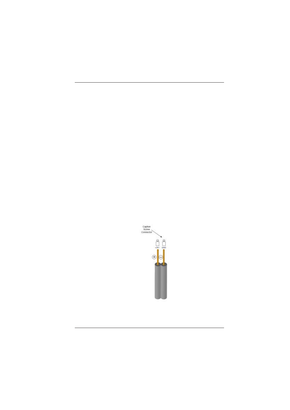
3.
Before connecting power wire to the LBC-H/V-T-WP unit,
make sure power supply is off. Prepare the Positive (+24V)
and chassis ground (CHASSIS to earth ground) tip of the
power wire as shown in Figure 3-8 to be directly plugged
into the captive screw +24VDC connector of the
LBC-H/V-T-WP unit.
Make sure the polarity of the connection is correct. Insulate
any exposed wire shields to prevent short circuits.
Figure 4-1
Power Connection