Ethernet, Thernet – BrightSign HD600 Hardware Guide User Manual
Page 7
BrightSign HD600
This information applies to a product under development. Its characteristics and specifications are subject to change without notice. Roku assumes no
obligation regarding future manufacturing unless otherwise agreed to in writing.
www.rokulabs.com
© Roku 2006
19
Button 8 input
20
Button 7 input
21
Ground
22
Button 4 input
23
Button 2 input
24
Ground
25
Button 0 input
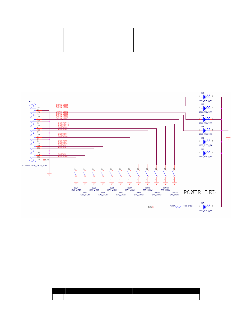
The following Diagram shows how to wire up a button and LED to each input/output (this is the
schematic of the Roku button/led board that we sell for development use). You of course can use as little
or as many of the inputs and outputs as you wish.
Ethernet
The HD600 has a standard RJ45 connector for 10/100 base T Ethernet. The Ethernet PHY chip we use is
capable of doing Auto-MDIX switching. This means that it will detect if a crossover is required, if for
example you tried to connect the HD600 directly to a PC without using a switch. If it detects that a
crossover is required, then the PHY chip will swap TX and RX pairs so that the connection will work
properly. The chip is also able to detect if an incorrect polarity cable is connected, and it will reverse the
polarity of the cable in that case. The pinout of the RJ45 is as follows (NOTE: This pinout is only
accurate for REVC and later HD600 boards, REVB has a hardware bug in this pinout):
pin Description
pin Description
1
TX+
2
TX-