Wiring the bus system, Can topology, Bus length – BECKHOFF FC5101 User Manual
Page 14
Eiserstraße 5 / D-33415 Verl / Telefon 05246/963-0 / Telefax 05246/963-149
14
Wiring the Bus System
Section summary:
CAN topology
Bus length
Drop lines
Star hub
CAN cable
Screening
Cable colours
FC510x: D-sub, 9 pin
BK51x0: 5- pin open style connector
LC5100 bus connection
Fieldbus Box: M 12 CAN socket
Notes related to checking the CAN wiring can be found in the Trouble Shooting section.
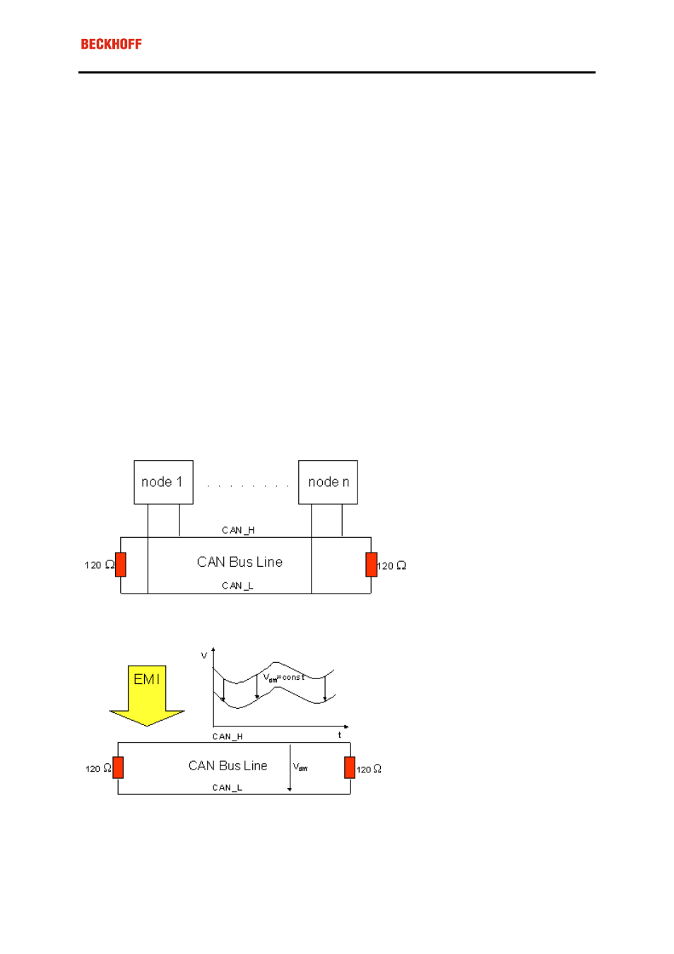
CAN topology
CAN is a 2-wire bus system, to which all participating devices are connected in parallel (i.e. using short drop
lines). The bus must be terminated at each end with a 120 (or 121) Ohm terminating resistor to prevent reflec-
tions. This is also necessary even if the cable lengths are very short!
Since the CAN signals are represented on the bus as the difference between the two levels, the CAN leads are
not very sensitive to incoming interference (EMI): Both leads are affected, so the interference has very little
effect on the difference.
Bus length
The maximum length of a CAN bus is primarily limited by the signal transit time. The multi-master bus access
procedure (arbitration) requires signals to reach all the nodes at effectively the same time (before the sampling
within a bit period). Since the signal transit times in the CAN connecting equipment (transceivers, opto-