Assembly – Dixon SpeedZTR 539 131301 User Manual
Page 8
8
ASSEMBLY
1
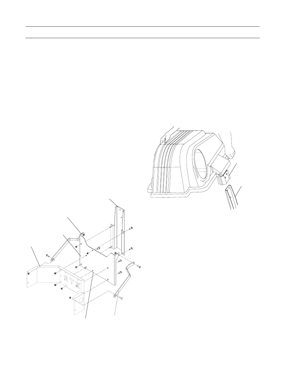
BAGGER SUPPORT ASSEMBLY
2
MOUNTING COVER ASSEMBLY TO
SUPPORT ASSEMBLY
NOTE: For ease of assembly, you may wish
assistance from another person for mounting the
cover assembly to mower.
1. Position cover assembly on ground behind
mower.
2. Lift and rotate cover to align the cover bracket
with hanger bracket and slide the cover down
until secure.
Support Strap Tab
Hanger Bracket
Drill One
11
/
32
hole
into engine guard
to match this hole
Engine Guard
Frame Bracket
Hanger
Bracket
1. Remove the side bolts on the engine guard.
2. Using bagger support as a template, drill one
11
/
32
hole into the engine guard at the center
bottom. (See illustration) Attach bagger
support to engine guard using with four
3
/
8
-16 x ¾ bolts and four
3
/
8
-16 nyloc nuts.
hardware removed in Step 1. Make sure
support strap tabs are facing to the rear.
3. Attach hanger bracket to bagger support with
four
5
/
16
-18 x 1 carriage bolts and four
5
/
16
nyloc nuts. See illustration.
4. Attach support straps to bagger support at the
support strap tabs, using two
5
/
16
-18 x 1 hex
head bolts and two
5
/
16
nyloc nuts.
5. Align engine guard with attached support and
hanger bracket to rear of mower. Secure the
opposite end of the support strap and the
engine guard to the sides ofthe mower with
two
5
/
16
-18 x 1 carriage bolts and two
5
/
16
nyloc
nuts.
Bagger Support
Support Strap