BECKHOFF AX5000 60 A - 170 A User Manual
Beckhoff, Servo drive ax5000
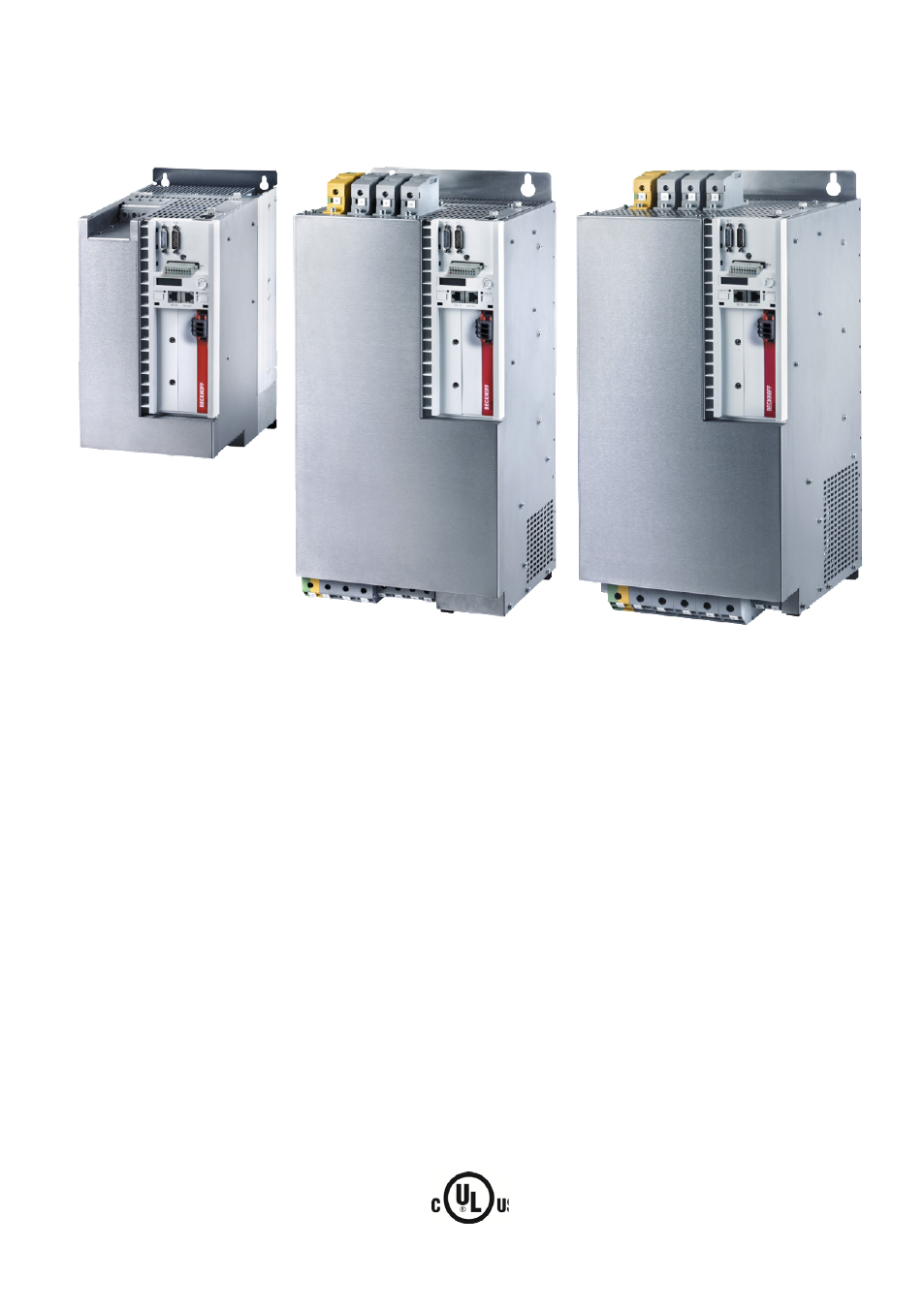
Table of contents
Document Outline
- 1 Foreword
- 2 Safety
- 3 Guidelines and Standards
- 4 Product description
- 4.1 Type code
- 4.2 Scope of supply
- 4.3 Name plate
- 4.4 Technical data
- 4.5 General overview (AX5160 and AX5172)
- 4.6 General overview (AX5190 and AX5191)
- 4.7 General overview (AX5192 and AX5193)
- 4.8 Overview of connectors/terminal points
- 4.8.1 X01 – voltage input
- 4.8.2 X07 – External brake resistor
- 4.8.3 X13 – Motor connection
- 4.8.4 X02 – DC link system (currently not permissible!)
- 4.8.5 X03 – 24 VDC supply
- 4.8.6 X04, X05 – EtherCAT connection
- 4.8.7 X06 – Digital I/Os
- 4.8.8 X11 – feedback, high-resolution
- 4.8.9 X12 – resolver/hall
- 4.8.10 X14 – motor brake and thermal contact
- 4.9 Dimensions
- 5 Installation
- 6 Important information for commissioning
- 7 Project planning – important information
- 8 Appendix