3 control-/status-byte, 1 control byte in process transfer – BECKHOFF KL5101-0000 User Manual
Page 13
Terminal configuration
KL5101
11
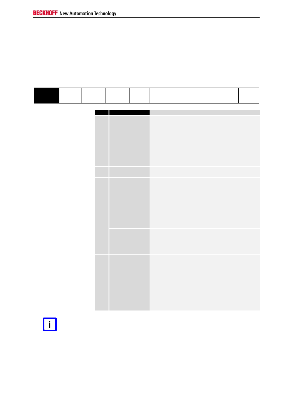
3.3 Control-/Status-Byte
3.3.1 Control byte in process transfer
The control byte is transferred from the controller to the terminal. It can be
used in the register mode (REG = 1) or in process data transfer (REG = 0).
Various actions are triggered in the the KL5101 with the control byte:
Bit
7 6 5
4
3
2
1 0
Name
REG=0 -
- -
En_Latch_Ext_n
Cnt_Set
EN_LAT_EXT
/
RD_PERIOD
EN_LATC
Bit
Bit
Function
3
En_Latch_Ext_n
The external latch input is activated for negative
edge. With the first external latch impulse after
validity of the EN_Latch_Ext_n bit, the counter value
in the latch register is stored. The pulses that follow
have no influence on the latch register when the bit
is set. Attention must be paid to ensuring that the
corresponding latch valid bit (Latch_Ext_Val) has
been removed from the terminal before alerting of
the zero pulse. This functionality is adjustable in the
feature register (default).
2
Cnt_Set
The counter is set to the value that is specified via
the process data with the rising edge of Cnt_Set.
1
En_Latch_Ext
The external latch input is activated for positive
edge. With the first external latch impulse after
validity of the En_Latch_Ext bit, the counter value in
the latch register is stored. The pulses that follow
have no influence on the latch register when the bit
is set. Attention must be paid to ensuring that the
corresponding latch valid bit (Latch_Ext_Val) has
been removed from the terminal before alerting of
the zero pulse. This functionality is adjustable in the
feature register (default).
RD_Period
The periods between two positive edges of the input
A are measured with a resolution of 200 ns. When
the bit is set, this period is output in the data bytes
D2, D3, D4. This functionality is adjustable in the
feature register.
0
En_Latch
The zero point latch (C input) is activated. The
counter value is stored in the latch register with the
first external latch pulse after validity of the En_Latch
bit (this has priority over En_Latch_Ext). The pulses
that follow have no influence on the latch register
when the bit is set. Attention must be paid to
ensuring that the corresponding latch valid bit
(Latch_Val) has been removed from the terminal
before the zero pulse is alerted (the Latch_Val bit
cannot be removed from the terminal until the C
pulse has a low level).
Note
For the external latch input:
The activation of the positive edge (En_Latch_Ext = 1) has priority to the
activation of the negative edge (En_Latch_Ext_n = 1).