Connector pin assignment, Data exchange – BECKHOFF BK5000 User Manual
Page 8
Connector Pin Assignment
4
BK5000
4
Connector Pin Assignment
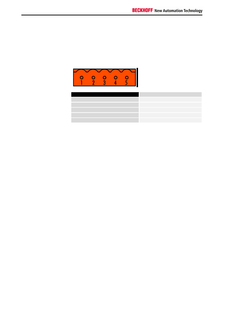
CAN-CAL Connector
Power supply
For Connecting the CAN bus cable the bus coupler comes with a 5pin
connector. Pin 1 is on the top side of the bus coupler. The pictures shows
the socket at the bus coupler. The power supply has to be connected at the
terminals on the right hand side of the bus couplers (labelled with 24 V and
0 V)
Pin assignment CAN-CAL connector
1
n.c.
2
CAN-H
3
GND
4
CAN-L
5
CAN-GND
Data Exchange
Channel enumeration
All input and output channels of the same kind are enumerated, counting
from the bus coupler onwards. So all analogue inputs are enumerated and
all analogue outputs get separate numbers. Enumeration starts with 0, so
the first channel of the first analog input terminal after the bus coupler has
the relative channel number 0. The second channel of this terminal gets
channel number 1, and number 2 is assigned to the first channel of the next
analog input terminal, assuming that the first terminal has two channels.
Analogue inputs and output data is 16 bit wide and transmitted in 2 Bytes:
first the LSB and then the MSB.
8 digital inputs form one
digital channel
Digital I/O data is transmitted in byte-wise. Therefore the digital I/Os are
combined in groups of eight that form one channel. The relatively first
digital input after the bus coupler is found in bit 0 of the first digital input
channel. The second input is found in Bit 1. The 7
th
digital input in the
terminal row is found in bit 6 of the first channel, and the 9
th
input is found in
bit 0 of the second digital input channel. If there are non-digital terminals in
between these are not considered for the digital channels.