Configuration of the bus coupler – BECKHOFF BK5000 User Manual
Page 7
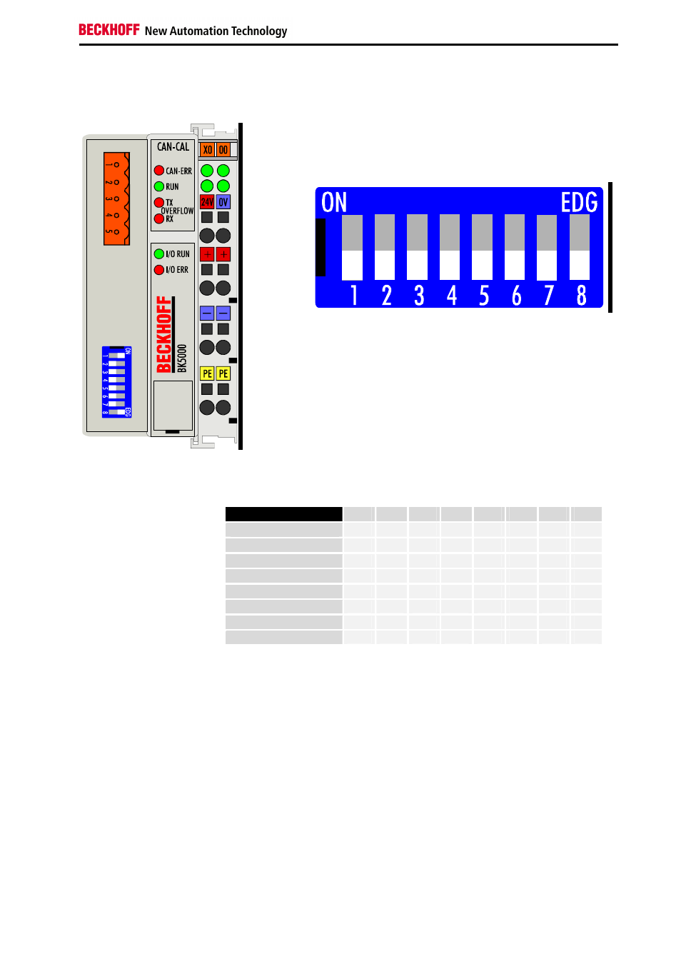
Configuration of the Bus Coupler
BK5000
3
Configuration of the Bus Coupler
All DIP-switches to off,
then power bus coupler
Switch all DIP-Switches to OFF and then power the bus coupler. The
four upper status LEDs are blinking. The baud rate is now selected
with the DIP-Switches 1 to 3. For details see table below.
Select baud rate
baud rate
1
2
3
4
5
6
7
8
1 MBit
off
off
off
500 kBit
on
off
off
250 kBit
off
on
off
125 kBit
on
on
off
100 kBit
off
off
on
50 kBit
on
off
on
20 kBit
off
on
on
10 kBit
on
on
on
Select node class
The node class is now configured with DIP switch 5. Off means node class
0 (without master). Switch 5 to ON means node class 2 (with DBT/NMT
master).
Store configuration
The configuration of the DIP switch settings 1, 2, 3 and 5 is stored as soon
as Switch 8 is switched to ON. Afterwards the LEDs remain on constantly.
Power down bus coupler
Select node ID
Switch on bus coupler
Now power down (switch off) the bus coupler and then select the node ID
with DIP switch 1 to 8. Switch 1 is the least significant bit 2
0
and switch 8 is
the most significant bit 2
7
. In switch position ON the Bit is set.
With node class 1 an ID between 1 and 255 can be selected. At node class
0 only IDs between 1 and 65 are allowed. The bus coupler is now ready for
operation and you can power it again.