BECKHOFF BK3000 User Manual
Page 53
Appendix
BK3xxx/LC3100
53
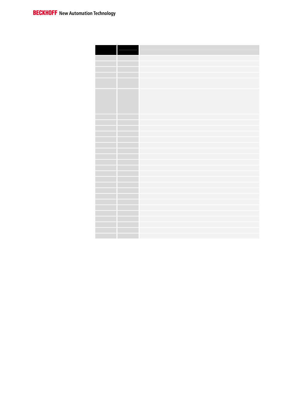
DPV1-Read
Slot
number
Index
Description
0
9
List of terminals 0 – 23 (table 9, register 0 – 23)
0
10
List of terminals 24 – 47 (table 9, register 24 – 47)
0
11
List of terminals 48 – 64 (table 9, register 48 – 64)
0
90
Terminal bus state register (table 90, register 0 – 20)
0
97
Error counter for synchronous input update (table 97, register
0)
0
98
Cycle time for cycle measurement (table 98, register 0-3)
Word 0: minimum cycle time (in 8 microsecond units)
Word 1: maximum cycle time (in 8 microsecond units)
Word 2: current cycle time (in 8 microsecond units)
Word 3: mean cycle time (in 8 microsecond units)
1
0-63
1
st
complex terminal, channel 0, register 0 - 63
1
64-127
1
st
complex terminal, channel 1, register 0 - 63
1
128-191
1
st
complex terminal, channel 2, register 0 - 63
1
192-255
1
st
complex terminal, channel 3, register 0 - 63
2
0-63
2
nd
complex terminal, channel 0, register 0 - 63
...
...
...
64
192-255
64
th
complex terminal, channel 3, register 0 – 63
65
0
1
st
complex terminal, channel 0: output process data
65
1
1
st
complex terminal, channel 1: output process data
65
2
1
st
complex terminal, channel 2: output process data
65
3
1
st
complex terminal, channel 3: output process data
65
4
1
st
complex terminal, channel 0: input process data
65
5
1
st
complex terminal, channel 1: input process data
65
6
1
st
complex terminal, channel 2: input process data
65
7
1
st
complex terminal, channel 3: input process data
66
0
2
nd
complex terminal, channel 0: output process data
...
...
...
128
7
64
th
complex terminal, channel 3: input process data
129
0
Output process data (bytes 0-15) of the digital terminals
129
1
Output process data (bytes 16-31) of the digital terminals
129
4
Input process data (bytes 0-15) of the digital terminals
129
5
Input process data (bytes 16-31) of the digital terminals