BayTech DS74 2012 User Manual
Page 7
Page
7
CABLING
RJ45 Cable
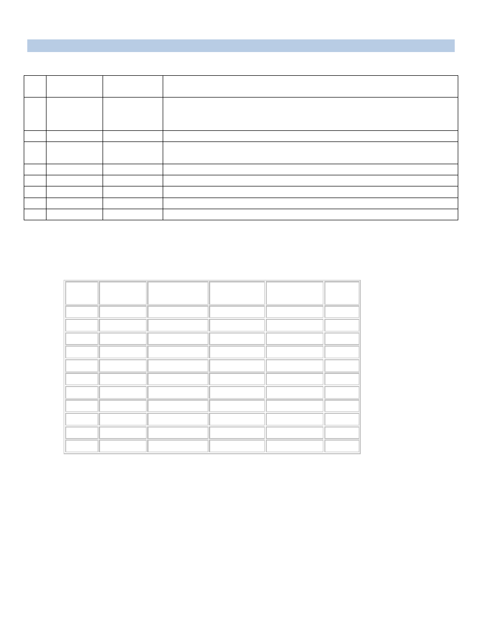
Control Module RJ-45 pin Signals
Pin
EIA 232
Signal
Signal
Direction
Description
1 DTR
Out
Handshake, Line Driver Inactive State = Low: -12V when port is selected
unless programmed differently. Used as a handshake line to enable/disable
the receiving of characters.
2 GND
Signal
Ground
3 RTS
Out
Handshake, Line Driver Inactive State = Low: -12 V when port is selected
unless programmed differently
4
TX
Out
Transmit (Data Out)
5
RX
In
Receive (Data In)
6
DSR
In
Handshake In. +12V when not used
7 GND
Signal
Ground
8
CTS
In
Used as a handshake line to enable/disable the receiving of characters.
Adapter signals
Listed are the pin specifications for the BayTech cable and adapters and the terminal COM ports:
Serial 1: Port Pin out Table
Signal RS-232
Port (DS)
RS-232 Port
(RPC)
COM Port
DE-9 Pin
COM Port
DB-25 Pin
Signal
DTR 1
1
4
20 DSR
GND 2
2
1 GND
RTS 3
3
7
5 CTS
TXD 4
4
3
2 RXD
RXD 5
5
2
3 TXD
DSR 6
N/C
6
6 DTR
GND 7
7
5
7 GND
CTS 8
8
4 RTS
DTR
4
DCD
DCD
8
1
8 DTR
RI 9
22