Time overcurrent pickup test, Ugh 34, O figure 34 – Basler Electric BE1-51/27R User Manual
Page 51
9137200999 Rev F
45
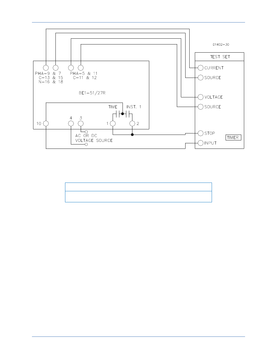
Figure 34. Test Setup for Sensing Input Type Y or Z (Two-Phase with Neutral Sensing)
Time Overcurrent Pickup Test
This test checks the minimum and maximum overcurrent pickup points of the time overcurrent element.
Note
During this test, disregard any indication on the test setup timer.
Step 1. Perform the preliminary instructions.
Step 2. Set the front panel TAP selector to A.
Step 3. Adjust the test set, for an overcurrent threshold having one of the following values:
(a)
0.5 for relays with Sensing Input Range 1, 2, or 4.
(b)
1.5 A for relays with Sensing Input Range 3 or 5.
Step 4. Slowly adjust the front panel TAP CAL control CCW until the front panel TIMING indicator
illuminates.
RESULT: For the phase minimum overcurrent pickup point of 0.5 A (Step 3a, above) or 1.5 A
(Step 3b, above) the front panel TAP CAL control should be near its maximum CCW limit.
Step 5. Adjust the front panel TAP CAL control fully CW to allow measurement of the actual
overcurrent pickup point at the A setting of the front panel TAP selector. Note that the front
panel TIMING indicator will extinguish. Do not disturb this setting.
Step 6. Slowly increase the current toward the value of the front panel TAP selector A setting until the
front panel TIMING indicator illuminates. Do not disturb this setting.
Step 7. Record the current reading and remove input current.
RESULT: The recorded value should be within
±5% of the front panel TAP selector A setting
for the phase minimum overcurrent pickup point for the time overcurrent.
BE1-51/27R
Tests and Adjustments