Commlink 5 technical guide, Loop communication setting, 6 operator interface – Auto-Zone Control Systems CommLink 5 Technical Guide, Installation Instructions for the CommLink 5 Communications Interface (Version 01G) User Manual
Page 6: Setting the commlink 5 setting communications, Mul t iple single loop
CommLink 5 Technical Guide
6
Operator Interface
Loop Communication Setting
Setting the CommLink 5
Setting
Communications
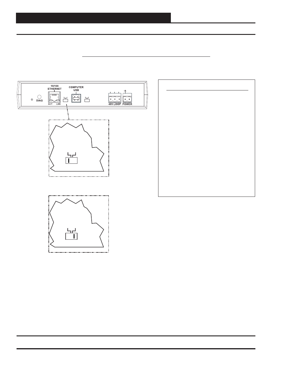
CommLink 5 Communications Setting
The Loop Switch Located On The Back Of The
CommLink 5 Housing Must Be Set Correctly For
Your Specific Application In Order For The
CommLink 5 To Function Properly.
The
Switch Setting Should Be Set To
“Multiple” In The Following Situation:
You Have A Single CommLink With
MiniLink(s) or MiniLink PD(s) Installed On
Your System.
The CommLink
5 Is Factory Set For Multiple Loop Applications.
Loop
The Loop Switch Setting Should Be Set To
“Single” In The Following Situation:
You Have A Single CommLink Without Any
MiniLinks Or MiniLink PDs Installed On Your
System.
MUL
T
IPLE
HIGH
SINGLE
LOW
BAUD
LOOP
R
(+)
24V
GND
SHLD
T(
-)
SERIAL #
MUL
T
IPLE
SINGLE
LOOP
Switch Set To Multiple
Loop Communications
MUL
T
IPLE
SINGLE
LOOP
Switch Set To Single
Loop Communications
Back of CommLink 5
Figure 2: Setting Loop Communications