Commlink 5 technical guide, Connecting the network – Auto-Zone Control Systems CommLink 5 Technical Guide, Installation Instructions for the CommLink 5 Communications Interface (Version 01G) User Manual
Page 13
CommLink 5 Technical Guide
13
Operator Interface
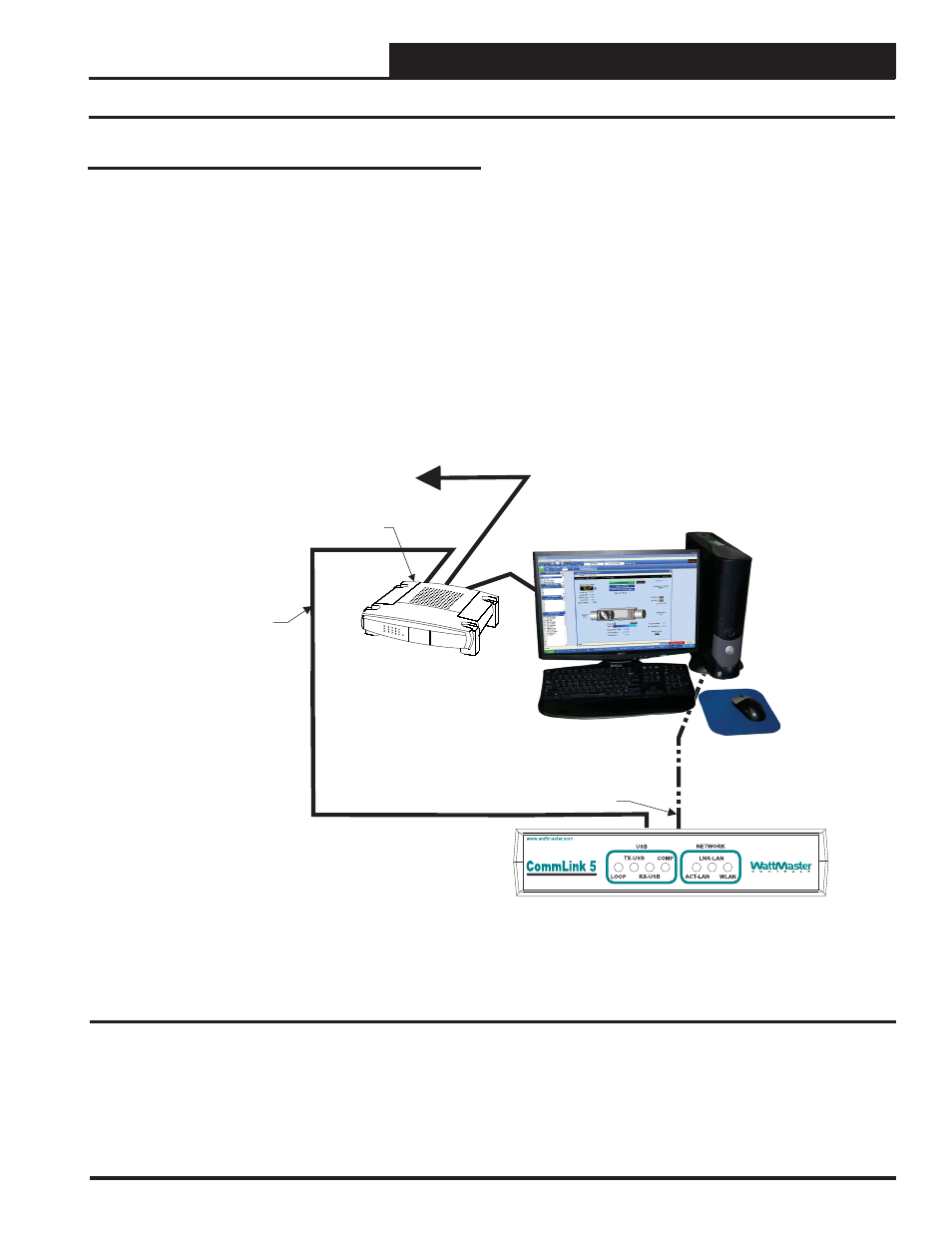
Connecting the Network
CommLink 5
Firewall
/
/Proxy Router
Ethernet Cable To Other
Nodes On Building LAN Or WAN
Ethernet Cable
Optional Direct
Computer Connection
To CommLink 5 Via Crossover
(Supplied with IP Module)
Personal Computer
Figure 4: Example Network Diagram of a Firewall or Proxy Confi guration
Proxy and Firewall Compatibility
Proxy and Firewall confi gurations
may become necessary
when the CommLink 5 is connected to a LAN/WAN that is pro-
tected by a commercially available Firewall, Proxy, or NAT enabled
router. Examples of these would include Cisco, NetGear, LinkSys,
or WatchGuard Technologies. Also, some ISPs provide IP Address
ranges that are already fi re-walled at the NOC or ISP Head-End.
Make sure that your IT Department or ISP can create a mapped TCP
port 39288 on your fi rewall/proxy to TCP port 39288 on the assigned
IP Address of the CommLink 5.
Only with proper confi guration of the Firewall/Proxy are connections
to the CommLink 5 from outside of the local area network going to
be possible. Check that the Firewall/Proxy TCP port 39288 is not
set to time out or reset after a specifi ed amount of time when there
is no traffi c from the remote PC.