Cv-c relay expansion board wiring, Cvcwir1.cdr oe351, Cv- c controller relay expansion board – Auto-Zone Control Systems Auto-Zone CV-C Controller Installation Guide (Version 01A) User Manual
Page 6
Notes:
C
O
N
T
R
O
L
S
FILENAME
DATE:
B. CREWS
DESCRIPTION:
PAGE
DRAWN BY:
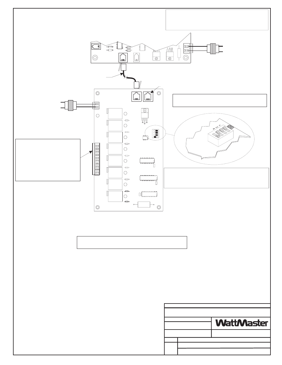
CV-C Relay Expansion Board Wiring
Line Voltage
Line Voltage
See Note 1
See Note 1
Required VA For Transformer
Each CV-C Controller = 20VA Max.
Required VA For Transformer
Relay Expansion Board = 20VA Max.
24VAC
24VAC
GND
GND
Caution!
Relay Expansion Board Must Have Address Switches Set As
Shown Or The Board Will Not Function.
Caution:
Disconnect The Modular Cable Between The CV-C Controller And The
Relay Expansion Board Before Removing Power From The Relay
Expansion Board. Reconnect Power And Then Reconnect The Modular
Cable Between The CV-C Controller And The Relay Expansion Board.
JOB NAME
1.)24 VAC Must Be Connected So
That All Ground Wires Remain
Common.
2.)All Wiring To Be In Accordance
With Local And National Electrical
Codes And Specifications.
07/08/99
CVCWIR1.CDR
OE351
1
Note:
Set-up, Programming And Monitoring Of The CV-C Controller Requires The
Use Of A Personal Computer And ZoneView AZ Software.
EXPANSION
SENSOR
PRESSURE
T'STAT
24VAC
GND
Relay Outputs R6 Thru R13 May Be User
Configured For The Following:
0 - Not Used (Nothing connected to this
output )
1 - Heating Stage
2 - Cooling Stage
3 - Humidifier Enable
4 - De-Humidifier Enable
5 - Scheduled Relay from Internal Schedule
6 - Scheduled Relay from External Schedule
(Only 1 Available!)
CV- C Controller
Relay Expansion Board
EXPANSION PORT
24VAC
IN
OUT
COM
Connect Expansion Board
to CV-C Controller
with Modular Cable
Not Used
POWER
U4
U5
U3
U1
RELAY 1
RELAY 2
RELAY 3
ADDRESS
RELAY 4
RELAY 5
RELAY 6
RELAY 7
RELAY 8
N.O.
CONT
ACTS
1-8
RELA
Y
COMMONS
9,10
Warning:
If One Transformer Is Used To Power The CV-C Controller And The
Relay Expansion Board, Polarity Must Be Strictly Observed. If The
Polarity Is Reversed, Serious Damage To Both Boards Will Result.