Cv-c controller wiring, Cvcwir1.cdr oe747, Address add address add – Auto-Zone Control Systems Auto-Zone CV-C Controller Installation Guide (Version 01A) User Manual
Page 4: Cv- c controller
Notes:
C
O
N
T
R
O
L
S
FILENAME
DATE:
B. CREWS
DESCRIPTION:
PAGE
DRAWN BY:
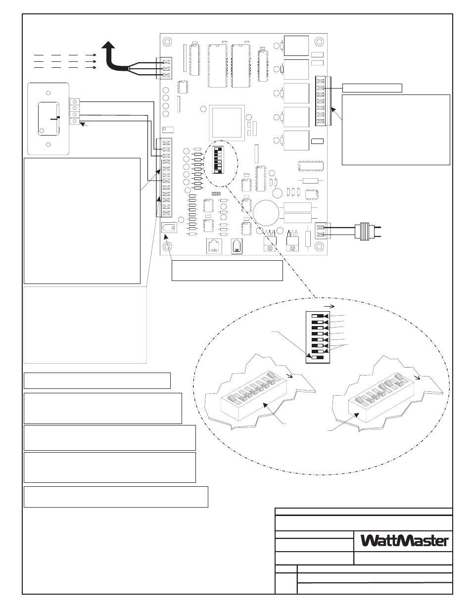
CV-C Controller Wiring
Line Voltage
See Note 1
R
SH
T
R
SH
T
R
SH
T
R
SH
T
All Comm Loop Wiring Is
Straight Thru
Required VA For Transformer
Each CV-C Controller = 20VA Max.
24VAC
GND
16
8
4
2
1
Caution!
CV-C Controllers Must Have Address Switches Set Between 1
And 30 When Used With CV or CV-EX Systems. Auto-Zone
Plus Systems Require That The Address Switches Be Set
Between 18 And 30.
Local Loop RS-485
9600 Baud
(See Note 3).
Connect To Next Controller And/Or
MiniLink On Local Loop
Address Switch Shown Is
Set For Address 1
Address Switch Shown Is
Set For Address 13
Controller
Address Switch
This Switch Must Be
In The ON Position
As Shown
These Switches Should Be
In The OFF Position
As Shown
Note:
The Power To The CV-C Controller Must Be Removed And
Reconnected After Changing The Address Switch Settings In Order
For Any Changes To Take Effect.
Caution:
Disconnect All Communication Loop Wiring From The CV-C Controller
Before Removing Power From The CV-C Controller. Reconnect Power
And Then Reconnect Communication Loop Wiring.
ADDRESS
ADD
ADDRESS
ADD
ADDRESS
ADD
The Address For Each Controller
Must Be Unique To The Other Controllers
On The Local Loop
JOB NAME
1.)24 VAC Must Be Connected So
That All Ground Wires Remain
Common.
2.)All Wiring To Be In Accordance
With Local And National Electrical
Codes And Specifications.
3.)AllCommunication Wiring To Be
2 Conductor Twisted Pair With
Shield. Use Belden #82760 Or
Equivalent.
07/08/99
CVCWIR1.CDR
OE747
1
Note:
Set-up, Programming And Monitoring Of The CV-C Controller Requires The
Use Of A Personal Computer And ZoneView AZ Software.
EXPANSION
SENSOR
PRESSURE
GND
7
AIN
AOUT2
AOUT1
AIN
GND
GND
5
AIN
AIN
AIN
4
3
2
T'STAT
24VAC
NETWORK
16
TOKEN
32
8
4
GND
AIN
1
12V
INPUTS
R
SHLD
T
COMM
1
2
YS101718
TUC5R PLUS
C
O
M
1-3
R5
C
O
M
4-5
R4
R3
R2
R1
R - Fan ON/OFF Only
GND
AUX
TMP
NORMAL
OVR
R
E
L
O
C
R
E
M
R
O
A
W
Room Sensor
Connection To
AUX Terminal is Reqd
Only When Sensor
Is Specified With
Slide Adjust Option
AIN2 Thru AIN5 & AIN7 May Be User
Configured For The Following:
0 - Not Used ( Nothing connected to this input)
1 - Slide Offset
(Requires Flush Mount Wall Sensor)
2 - Supply Air Temperature
3 - Return Air Temperature
4 - Mixed Air Temperature
5 - Outdoor Air Temperature
(Will broadcast to ALL other controllers)
6 - Humidity Sensor (4-20 mA scaling)
7 - Humidity Sensor (0-5 VDC scaling)
8 - CO² Sensor (4-20 mA scaling)
9 - CO² Sensor (0-5 VDC scaling)
10- Relief Pressure Sensor
(Requires 0-5 VDC ±0.3" WG Sensor)
11 - Dirty Filter Contact (Normally Open)
12 - Alarm Contact (Normally Open)
13- Alarm Contact (Normally Closed)
14- Fan Status Contact (Normally Open)
AIN6 (Phone Jack) Can Only Be Configured
For An Airflow Sensor And Is Used For
Status or To Verify Fan Operation Only
Relay Outputs R2 Thru R5 May Be User
Configured For The Following:
0 - Not Used (Nothing connected to this
output )
1 - Heating Stage
2 - Cooling Stage
3 - Humidifier Enable
4 - De-Humidifier Enable
5 - Scheduled Relay from Internal Schedule
6 - Scheduled Relay from External Schedule
(Only 1 Available!)
AOUT1 & AOUT2 May Be User Configured For
The Following:
0 - Not Used (Nothing connected to this output)
1 - Economizer
(Requires Supply or Mixed Air Sensor
2 - Relief Fan VFD Signal
(Requires Relief Pressure Sensor)
3 - Chilled Water Valve
(Requires Supply Sensor)
4 - Hot Water Valve (Requires Supply Sensor)
5 - Humidification / De-Humidification
(Requires Humidity Sensor)
Note: All Temperature Sensors Must Be Thermistor Type III
Which Provide 10K Ohms Resistance @77 Deg. F
CV- C Controller