Cv-c humidity sensor wiring, Cvchumid1.cdr auto-zone, Cv- c controller – Auto-Zone Control Systems Auto-Zone CV-C Controller Installation Guide (Version 01A) User Manual
Page 5
Notes:
C
O
N
T
R
O
L
S
FILENAME
DATE:
B. CREWS
DESCRIPTION:
PAGE
DRAWN BY:
CV-C Humidity Sensor Wiring
JOB NAME
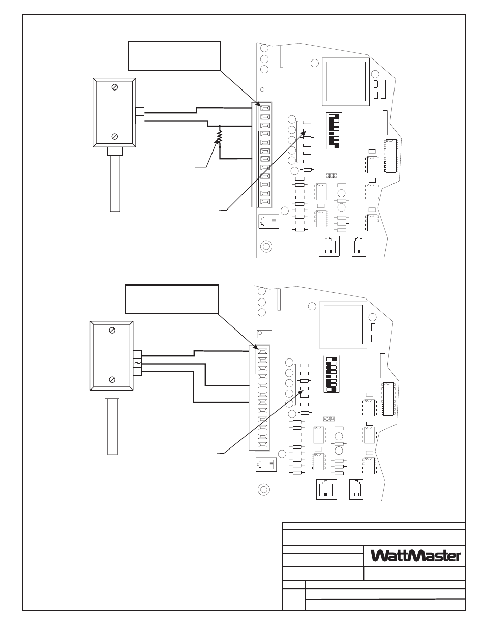
1.)24 VAC Must Be Connected So
That All Ground Wires Remain
Common.
2.)All Wiring To Be In Accordance
With Local And National Electrical
Codes And Specifications.
06/01/00
CVCHUMID1.CDR
Auto-Zone
1
CV- C Controller
CV- C Controller
EXPANSION
EXPANSION
SENSOR
SENSOR
PRESSURE
PRESSURE
GND
GND
7
7
AIN
AIN
AOUT2
AOUT2
AOUT1
AOUT1
AIN
AIN
GND
GND
GND
GND
5
5
AIN
AIN
AIN
AIN
AIN
AIN
4
4
3
3
2
2
T'STAT
T'STAT
NETWORK
NETWORK
16
16
TOKEN
TOKEN
32
32
8
8
4
4
AIN
1
AIN
1
12V
12V
PU1
PU1
PU2
PU2
PU3
PU3
PU4
PU4
PU5
PU5
PU7
PU7
INPUTS
INPUTS
1
1
2
2
250 ohm Resistor
Installed Between the
AIN2 Input Terminal
and the GND Terminal
Resistor Must be of 1%
Accuracy or Better
+
+
-
-
4-20ma
Sensor
0 - 5 VDC
Sensor
The Pull-up Resistor (PU2),
for the Associated In
Must be Removed When a
4-20ma Sensor is Used
put (AIN2),
The Pull-up Resistor (PU4),
for the Associated In
Must be Removed When a
0-5 VDC Sensor is Used
put (AIN4),
Note: Terminal that is Labeled
“12V” on the Terminal Block
has been Electrically Modified
and is Actually 24 Volts
Note: Terminal that is Labeled
“12V” on the Terminal Block
has been Electrically Modified
and is Actually 24 Volts
4-20ma Sensor Installation
0-5VDC Sensor Installation