3f33_^db_\\ub, 1ed_j_^u3_^db_\cicdu]c – Auto-Zone Control Systems Auto-Zone CV-C Controller Installation Guide (Version 01A) User Manual
Page 3
1ed_J_^U3_^db_\CicdU]c
Form: AZ-CVC-DS-01A-599-0101
Page
1 of 1
Technical Data
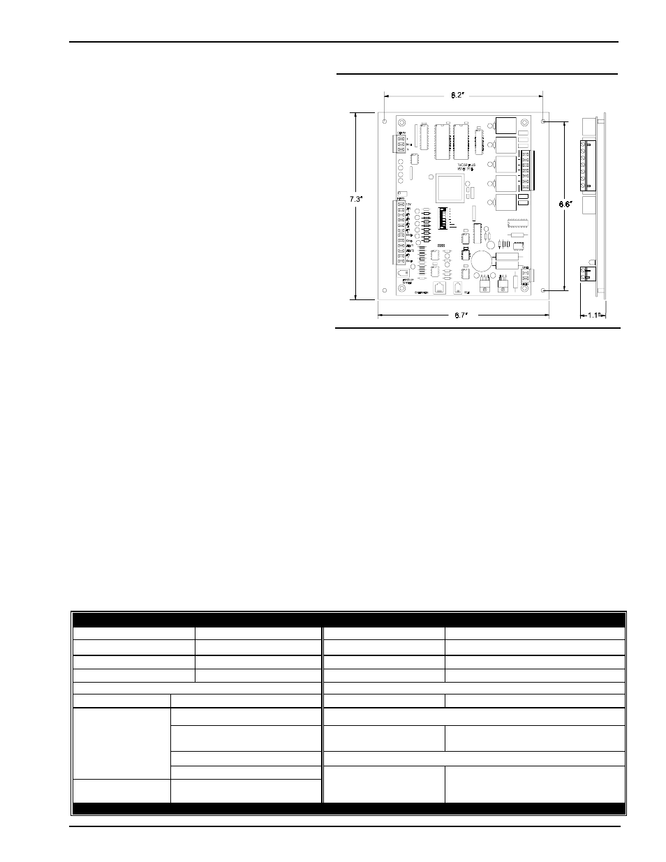
CV-C Controller
Power
24 Volt AC
Weight
1.5 lb.
Power Consumption
12 VA Maximum
Network Connection
RS-485
Operating Temp
10
°
F to 149
°
F
Protocol
HSI Open Protocol Token Passing
Operating Humidity
90% RH Non-Condensing
Communications
RS-485 - 9600 Baud
Inputs:
Outputs:
Quantity Available
Types
Quantity Available
Types
Type III-10kohm Sensor
Binary
0-10 VDC Sensor
0-5 VDC Sensor
5
Onboard Relays (2 Amp @ 24 VAC)
N.O. Contacts with Suppressors
4-20mA Sensor
Analog
6
Binary Contact Closure
1
Modular Phone Jack For
Optional Airflow or SP Sensor
2
0-10 Volt DC Out
WattMaster reserves the right to change specifications without notice
One Year Warranty
Relay Outputs
Only Relay Output #1 (Fan On/Off Only) has a specific function
that cannot be changed. All other outputs are user configurable
in one of the following modes:
•
0 - Not Used (Nothing connected to this output )
•
1 - Heating Stage
•
2 - Cooling Stage
•
3 - Humidifier Enable
•
4 - De-Humidifier Enable
•
5 - Scheduled Relay from Internal Schedule
•
6 - Scheduled Relay from External Schedule (Only 1
Available!)
There are a total of 12 relays that can be configured. Four are
found on the Controller itself (R2 - R5) and the remaining eight
(R6 - R13) are found on the Optional Relay Expansion Board that
can be connected to the PJ2 expansion input.
Mounting
The CV-C Controller is provided with an integral backplate for
mounting inside of a control enclosure. An optional factory control
enclosure for the CV-C Controller is available.
Analog Outputs
There are two Analog Outputs available on this
controller. They are both user configurable as follows:
•
0 - Not Used (Nothing connected to this
output)
•
1 - Economizer (Requires either Supply Air or
Mixed Air Sensor)
•
2 - Relief Fan VFD Signal (Requires Relief
Pressure Sensor)
•
3 - Chilled Water Valve (Requires Supply
Sensor)
•
4 - Hot Water Valve (Requires Supply Sensor)
•
5 - Humidification/De-Humidification
(Requires Humidity Sensor)
Description
The CV-C Controller is a configurable controller that
allows for user configurable inputs and outputs. CV-C
Controllers also have provisions for mounting a Relay
Expansion Board to provide additional heating or cooling
staging capability.
Analog Inputs
Only Analog Input #1 (Space Temp Sensor Only) and
Analog Input #6 (Airflow Sensor Only) have a specific
function that cannot be changed. All other inputs are user
configurable in one of the following modes:
•
0 - Not Used ( Nothing connected to this input )
•
1 - Slide Offset (Requires Flush Mount Wall
Sensor with this Option)
•
2 - Supply Air Temperature
•
3 - Return Air Temperature
•
4 - Mixed Air Temperature
•
5 - Outdoor Air Temperature (Will broadcast to
ALL other controllers)
•
6 - Humidity Sensor (4-20 ma scaling)
•
7 - Humidity Sensor (0-5 VDC scaling)
•
8 - CO² Sensor (4-20 ma scaling)
•
9 - CO² Sensor (0-5 VDC scaling)
•
10 - Relief Pressure Sensor (Requires 0-5 VDC
±0.3" WG Sensor)
•
11 - Dirty Filter Contact (Normally Open)
•
12 - Alarm Contact (Normally Open)
•
13 - Alarm Contact (Normally Closed)
•
14 - Fan Status Contact (Normally Open)
3F33_^db_\\Ub